


Operating Manual - VCM-88, VCM-88E, RD-8, RW-8 Level Controllers
6
5.7 Master Output and Channel Pass Through
The VCM-88(E) can be used as an eight-in/one-
out remote level control for personal monitor mixing using
the Master Output. Multiple VCM-88(E) units can be daisy
chained to produce several unique mixes from the same
program source. To simplify cabling for this application,
the VCM-88(E) has the ability to internally pass each
channel’s input signal directly to its output jack, disabling
that channel’s direct VCA output but eliminating the need
for special “Y” cables. The passed-through channel’s VCA
output is automatically summed to the 200 Ohm pseudo-
balanced Master Output along with other channels for fi-
nal output. The gain from any one input channel to Master
Output is -6dB so that a mix of several audio channels will
have approximately the same volume as one of the input
channels. See section 8.2 for channel pass-through details.
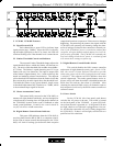
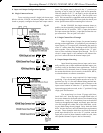
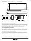
5.8 DC Control
A 15 pin female D-Sub connector on the back panel
(12-position Euroblock on the VCM-88E) is used for DC
control of the eight VCA channels and Master Attenuation,
providing a simple and cost-effective method for custom
control of the VCM-88(E). Most electronics hardware
stores will have the male connector complement. The ref-
erence DC voltage is also provided, thus requiring only the
male connector, wire, and a 10K ohm potentiometer for
each channel to control audio levels from any reasonable
distance. See section 9.3 for DC Control details.
5.9 Remote Control Data Input
This connector is used for remote control by the
Ashly RD-8 or RW-8, or other third party controllers. AMX
and Crestron are companies which manufacture touch-
screen computer interfaces for a variety of control applica-
tions, including the VCM-88(E). AMX and Crestron pro-
vide a hardware interface which uses the XLR Data In con-
nector on the VCM-88 and the Remote RD/RW-8 Euroblock
connector on the VCM-88E. See section 9.1 for AMX and
Crestron interface details.
5.10 Device ID Select
Each VCM-88(E) can be addressed to one of 16
devices, allowing for control of up to 128 channels (16 x 8)
from a single data line. The device ID on the VCM-88E is
selected in binary format from the Device ID DIP switch
on the rear panel. The device ID on the VCM-88 is inter-
nally selected with jumpers. See section 9.5 for Device ID
Select DIP switch settings or internal jumper locations.
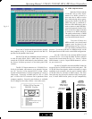
5.11 RS-232 Input
RS-232 is a bi-directional serial communications
connection which allows computer devices to control other
hardware. Ashly Protea System Software (see section 9.4)
uses RS-232 to control the VCM-88(E), and other third party
sources may use RS-232 as well.
While both the VCM-88 and the VCM-88E have
dedicated RS-232 input jacks, only the VCM-88E RS-232
input is truly bidirectional. RS-232 data is read into the
memory of the VCM-88E and stored, then read back from
memory to get an actual snapshot of the current data set-
tings. This is especially useful to upload to Protea System
Software the current settings of a VCM-88E.
The VCM-88 data is unidirectional in receiving
data only, meaning there is no RS-232 data out from the
unit.
5.12 RS-232 Mode Switch (VCM-88E only)
The RS-232 mode switch is pushed in only when
the VCM-88E RS-232 Input is connected to a PC, and an-
other unit is connected to the Slave Data connector.
1210
10K CW
Pin 1-9
CAUT I ON
RISK OF ELECTRIC SHOCK
DO NOT OPEN
RS-232
VCM-88E
Made In USA
Risk of Electric
Shock. Do
Not Open
CAUTION