


Operating Manual - VCM-88, VCM-88E, RD-8, RW-8 Level Controllers
12
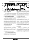
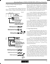
below). The Slave Data Out from the first unit is connected
to the Slave Data In on the next unit, and so on, with the
Slave Data Out from the last unit returning to the Slave
Data In on the first. A serial RS-232 cable is then connected
to the first unit, and the RS-232 switch is set to Multiple
RS-232 mode on this first unit only. (Note: the RS-232
switch must be set to standard mode on all other units.) All
units must be set to the same Protocol, such as Protea Soft-
ware, if that is the control method implemented.
The Slave Data signals are fully MIDI hardware
compliant, and standard MIDI controller messages may be
implemented when MIDI Protocol is selected. MIDI Con-
tinuous Controller #42-49 are used to control the level of
VCM-88(E) channels 1-8 respectively. Controller level
(0-127) yields a channel level of -75dB to +20.25dB, in
0.75dB steps, where 100 = 0dB. MIDI 5-pin DIN compat-
ibility is as follows:
Slave Data Pin MIDI signal 5-pin MIDI DIN
Slave In + MIDI In + pin #4
Slave In - MIDI In - pin #5
Slave In NC
(MIDI shield - float at input, per MIDI spec)
Slave Out + MIDI Out + pin #4
Slave Out - MIDI Out - pin #5
Slave Out G MIDI Shield pin #2
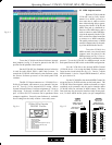
Note: whenever Ashly Protea System Software is
used the Protocol must be set to Protea Software on all units.
If problems occur, be sure to check that the proto-
col is selected to MIDI, that the VCM-88(E) has been se-
lected to the correct device (MIDI Channel), that the cor-
rect continuous controller number is being used for the
desired audio channel, and that the controller value is cor-
rect.
10. Troubleshooting Tips
10.1 No Output
Check AC power - is green power LED indicator
on? Check input/output connections - are they reversed?
Is the Master Attenuator control turned fully up? Are re-
mote controller channels switched on? Are the input/out-
put jacks configured correctly (one jack insert versus two
jacks) for the application?
10.2 Very Little Output Signal
Are the yellow Limiter Threshold indicators on
often? Rotate the recessed Threshold controls clockwise
to allow greater output signals to pass unlimited. Check
the Master Attenuator control - normally this control should
be fully clockwise at 0dB. Check the RD-8 remote con-
troller -the fader levels should normally be operated around
0dB.
10.3 Distorted Sound
The maximum input signal level is +23dBu =
10.95Vrms. Above this input level, input clipping distor-
tion will occur. Also, if the input signal level plus the gain
set by the remote controller goes above +23dBu, output
clipping distortion will result.
10.4 Excessive Hum or Noise
Hum and buzz noise is usually caused by a “ground
loop” between audio components. Try using balanced in-
put and output connections between the VCM-88(E) and
other components in the system. Also, try to power all com-
ponents in the system from a single AC branch circuit.
Noise can also be caused by a large amount of gain
applied to an insufficiently low input signal. The VCM-
88(E) is not designed to feed microphones directly into the
inputs without a mic preamp first. The VCM-88(E) is es-
sentially a line level unity-gain device, meaning it is de-
signed to be fed by a nominal 0dBu line level signal and its
output should typically be 0dBu in level. To ensure proper
gain structure in your sound system, press the remote dis-
able switch in and rotate the Master Attenuator control fully
clockwise so that all VCM-88(E) channels are at unity gain.
Adjust your signal source which precedes the VCM-88(E)
for nominal 0dBu signal levels, then push the Remote Dis-
able switch out for remote controllability.
If you still have problems, contact your Ashly
dealer or call Ashly direct at (800) 828-6308.