


Page - 8 Operator Manual – PE Series Amplifiers
Copyright© 2005 – Ashly Audio Inc.
Operation
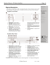
The amplifier’s On/Off Switch is a rocker-type switch located on the left side of the front
panel. Turning on the amplifier initiates start-up by activating the inrush current limiter.
During power up, the Clip and Signal LEDs from both channels will light up in red for a few
seconds.
When using the remote On/Off function, the main On/Off switch must remain in the On
position. See page 11 for more information on remote On/Off connections.
NOTE: The power switch does NOT isolate the appliance from mains. Make sure the mains
power socket or an alternative disconnect device is near by and easily accessible. When the
amp is connected to mains, the line-filter and the input of the silicon-controlled rectifier
(fuse) are energized.
2 Channel (Stereo) Mode
In this mode, the amplifier’s two channels operate fully independent of each other. Each
signal enters the unit and is amplified separately.
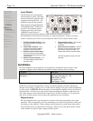
Parallel-Mono Mode
In this mode, a single input signal (connected to channel 1) is connected to the two output
channels. The output terminals of the two channels are configured in parallel using an
internal relay. The (single) load is connected either to the output of channel 1 or to that of
channel 2 (as if in stereo). While the total output of the amplifier remains the same and the
output voltage level is also the same as in stereo operation, the minimum impedance that
can be connected is reduced by half because the current capability is doubled. Only the
Channel 1 attenuator is active. The Channel 2 attenuator should be turned down to zero.
This mode is useful when identical loudspeakers are to be operated with the same power.
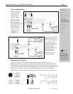
IMPORTANT: When connecting speaker cabinets in parallel, always use all the contacts
in both SPEAKON connectors. If not, this can cause permanent damage to the connectors
and considerably reduce performance.
Bridged Mono Mode
In this mode, a single input (connected to channel 1) is connected to the two output
channels that have been ‘Bridged” together. Each output channel processes the signal, but
the polarity of channel 2 is reversed. The (single) load is connected between the two
positive channel outputs using a suitably connected SPEAKON connector. While the total
output of the amplifier remains the same, both the available output voltage and the
minimum impedance that can be connected are doubled, as compared with stereo
operation. Only Channel 1 is active. A signal feeding Channel 2 will have no effect on the
output.
WARNING! In Mono-Bridge mode RMS output voltages as high as 230 V. Wiring to
the speaker loads must conform to NEC Class 3 safety standards or its equivalent. All
customer specific cables should only be manufactured by qualified personnel.
WARNING! Terminals marked with are HAZARDOUS LIVE. External wiring to
these terminals/connectors requires installation by trained personnel, or pre-
manufactured cables.
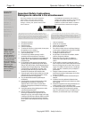
Important Safety
Instructions – 2
Introduction - 3
The PE Series - 4
Physical Description - 5
Installation – 6
Operation – 8
2 Channel Mode
Parallel Mode
Bridged Mode
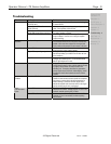
Troubleshooting - 9
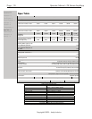
Spec Table - 10
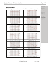
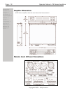
Measurements - 11
Dimensions - 12
Warranty - 13