


Operator Manual – PE Series Amplifiers Page - 11
All Rights Reserved Rev 3.1 0506
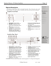
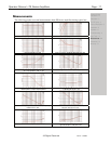
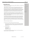
Measurements
The following graphs are actual measurements from PE-Series amplifiers during typical use.
Gain vs. frequency, Ch1, Ch2 - (typical performance) Gain vs. frequency / positions of HPF, Ch1, Ch2
Phase vs. frequency, Ch1, Ch2 Phase vs. frequency / positions of HPF-Switch, Ch1, Ch2
Output impedance vs. frequency @ 1 Amp RMS injected current
(Ch1, Ch2) equivalent 11 m + 2,1 μH
THD+N @ 1 kHz, 8 load vs. input voltage, Ch1, Ch2
Damping factor into 8 , Ch1, Ch2 equation: damping factor =
loaded impedance / amplifier output impedance
THD+N vs. frequency (BW 22 kHz),
10 dB below clip, 8, Ch1, Ch2
CCIF difference frequency method (10,5 kHz and 11,5 kHz) vs. input
level @ 8 , Ch1, Ch2
SMPTE intermodulation distortion (60 Hz and 7 kHz)
@ 8 vs. input level, Ch1, Ch2
Common mode rejection ratio (Ch1, Ch2) Channel separation vs. frequency
@ 10 W / 8 (Ch1 => Ch2, Ch2 => Ch1)
Important Safety
Instructions – 2
Introduction - 3
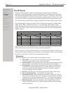
The PE Series - 4
Physical Description - 5
Installation – 6
Operation – 8
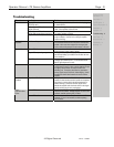
Troubleshooting - 9
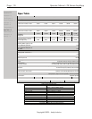
Spec Table - 10
Measurements - 11
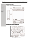
Dimensions - 12
Warranty - 13