


Operator Manual – PE Series Amplifiers Page - 5
All Rights Reserved Rev 3.1 0506
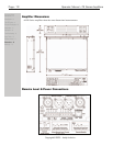
Physical Description
Each model in the PE-Series is 2RU, and weighs 20 pounds. They all share the same overall
physical design. The model number is indicated in the lower left corner of the front panel
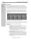
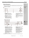
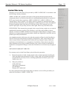
Amplifier Front Panel
1. Mounting Holes – For rack mounting.
2. Power Switch – Switches the unit on or off
3. Status LEDs – Indicate status of: Power,
Standby, Protect, Operating Mode and Comm
link
4. Air Inflow Vents – Cool air enters here
5. Channel Controls – Channel control area
6. Signal LEDs – The lowest LED will begin to
light when the output voltage reaches
approximately 4 volts. When clipping occurs
the Clip LEDs will begin to flash. If clipping
becomes severe the LEDs will remain on and
the amplifier will go into protect (mute) mode
until the signal is fixed.
7. Fault Indicators – These LEDs indicate if the
amplifier has entered a temperature or current
fault mode and will remain lit until the fault is
corrected.
8. Channel Attenuators – For adjustment of the
input signal.
Amplifier Rear Panel
1. Input Ground Lift – This switch isolates or
connects the signal ground to the power ground
2. High Pass Filter (both channels) – This switch
sets the High Pass Filter for each channel to
30Hz, 50Hz or Off. Depending on your system
set-up, there may be an audible "pop" when
engaging the HPF. It is recommended that you
operate these switches with the amplifier off.
3. Operating Mode – This switch selects the
amplifier’s operating mode (Bridge, Stereo, or
Parallel). NEVER OPERATE THIS SWITCH
WITH THE AMPLIFIER ON.
4. Input Gain – This switch sets the amplifier gain
to 26dB, 32dB, or 1.4V sensitivity.
5. Clip Limiter – This switch sets the clip limiting
circuitry to Off, Slow or Fast.
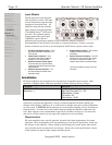
6. Input Module – Details on the next page
7. Cooling Air Outflow Vents – These vents
must remain open and unobstructed at all times
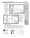
8. Speakon™ Output Connectors – These
connectors provide a convenient and fast
connection to your speakers.
9. Screw Terminal Output Connectors – Only
on models 800 & 1200, these traditional
connectors can be used in tandem with
(impedance dependent) or in lieu of the
Speakon output connectors
WARNING: Do not remove the mains connector ground. It is illegal and dangerous.
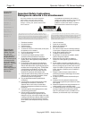
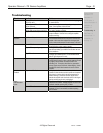
Important Safety
Instructions – 2
Introduction - 3
The PE Series - 4
Physical Description - 5
Front Panel
Rear Panel
Input Module
Installation - 6
Operation - 8
Troubleshooting - 9
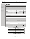
Spec Table - 10
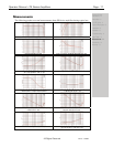
Measurements - 11
Dimensions - 12
Warranty - 13
Terminals marked
with are HAZARDOUS
LIVE. External wiring to
these terminals/
connectors requires
installation by trained
personnel, or pre-
manufactured cables