


320A
Compellor
Page 26
9. Appendices
lines are the same. They both need two conductors.
What makes a system unbalanced is when one of
the wires is formed into a tube that wraps around
the other conductor, without touching it, such that
the outer conductor can be said to “shield” the inner
conductor. This describes all of the coaxial cable used
for video, cable-TV and radio as well as most of the
high delity audio cables.
Balancing
If both conductors are identical insulated wires that
are twisted together, then they form a balanced line.
This describes telephone lines, microphone cables,
and most professional audio cables. Typical balanced
cables include an additional shield wrap around the
twisted pair, but this is not strictly required for bal -
anced lines to work properly.
Many people, because they have more experience
with unbalanced wiring, think that balanced is
confusing. Believe it or not, balanced lines are really
easier to understand than unbalanced. There is no
grounding issue with balanced, and the way it works
is perfectly natural and simple. Balancing naturally
rejects hum and noise and eliminates all sorts of
complications in interfacing.
Balanced transmission works something like this.
Your balanced input stage looks at the two wires
and detects only the potential (voltage) dierence
between them. Anything that is the same on the two
wires (for all practical purposes as seen measuring
from ground) is called a common mode signal and
Appendix A: Balanced and Unbalanced
Lines and Operating Levels
Interfacing all types of equipment with balanced and
unbalanced lines and can sometimes be trouble -
some. First you have to somehow connect balanced
to unbalanced and then you have to deal with dif -
ferent levels. This tutorial will teach you about the
principles of balanced and unbalanced lines, wiring
standards, and how to eectively interface them.
Standards
Professional audio equipment usually comes
equipped with inputs and outputs that are balanced
using 3-pin XLR connectors and sometimes 1/4 inch
phone jacks as well. This equipment most often is
designed to operate at +4dBu, a professional indus -
try standard. That translates to a magnitude of 1.23
volts RMS (Root-Mean-Squared).
Consumer gear has unbalanced I/O as standard, usu -
ally on RCA jacks. The normal operating signal level
follows the IHF (Institute of High Fidelity) standard
of -10dBV, or 0.316 volts (316mV) RMS. Converting
sa emas eht eb ot tuo skrow siht ,snoisnemid uBd ot
-7.79dBu. There is therefore a dierence of 11.79dB
between pro and consumer operating levels.
Grounding
There is the notion that some king of earthly “ground”
exists out there that sinks all the noise and acts as
some kind of a shield. You see wires connected to
ground rods and water pipes that are supposed to
get a good ground. This is not a correct interpreta -
tion of grounding from an audio standpoint. Proper
grounding of equipment and wiring is important and
you will gain a better understanding of that as you
read along.
Balanced -vs- Unbalanced
Every audio signal is connected through a circuit. The
circuit must contain two conductors to create a com -
plete return path. In other words, a signal voltage is
conducted to a piece of equipment by injecting a cur -
rent into a wire. That current has ow though to the
destination through the wire and return back to the
source through another wire. Since audio is an alter -
nating voltage, swinging through negative and posi -
tive polarity, the current through the two conductors
changes direction each alternate half cycle. Which
wire is the source and which is the return alternates
accordingly. In this regard, balanced and unbalanced
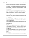
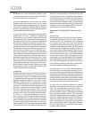
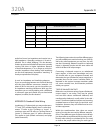
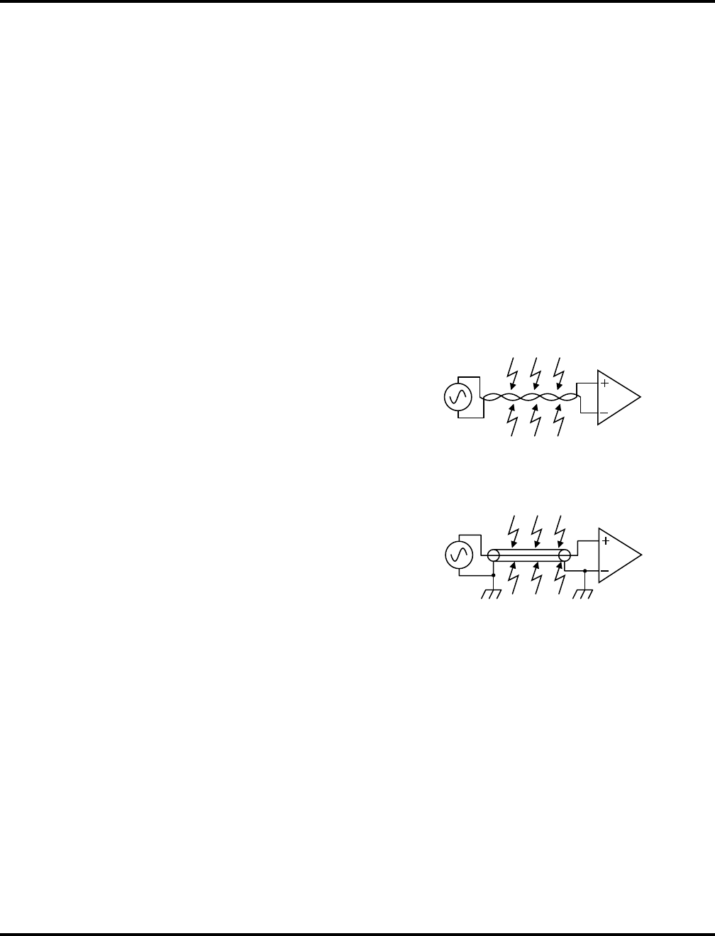
Figure 1 Balanced Line Model
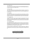
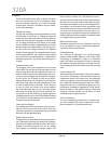
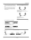
Figure 2 Unbalanced Line Model