


320A
Compellor
Page 12
Installation should be performed only by qualified individuals. It is the installer’s responsibility
to insure his personal safety and the safety of others in the work area. It is never a good idea
to work alone in the vicinity of high power electrical and radio frequency equipment.
4.10 Remote Connector
Remote control, a feature of the Models 320A and 323A.
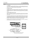
4.11 Reference Level Setting
The Compellor should be normalized to match the operating level of your system. When the
Compellor is properly matched to the system reference level, then the Compellor’s meters
will match the system meters and the internal dynamic range of the Compellor will be opti-
mized.
Normalizing the Compellor is accomplished by a rear panel REF LEVEL switch provided for
each channel. Two standard reference levels of -10dBV and +4dBu are available. Simply
set the switches as required.
.level gnitarepo ruoy ot gnittes tsesolc eht tceles ,level gnitarepo dradnatsnon a evah uoy fI
For DAT machines and other digital media that define operating levels according to a maxi-
mum level rather than an average level, we have found the -10dBV position most often pro-
vides the correct match.
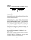
4.12 Input Connections
The input impedance is 20 kilohms and the Compellor will not significantly load the source
when the unit is in-line. Inputs are made by means of 3-pin female XLR jacks. Pin connec-
tions follow conventional standards. Pin 1 is connected directly to chassis ground. Signal
pins 2 and 3 may be used either as pin-2 positive or pin-3 positive as you wish. Current U. S.
and international industry standards call for using pin-2 as the positive polarity lead.
For unbalanced use, tie pin 3 to pin 1 for the ground and use pin 2 as “hot”.
Whether using balanced or unbalanced wiring, be sure to follow the same connection scheme
for both channels of the input and output wiring to avoid audio phasing problems.
Interfacing with unbalanced sources can sometimes be improved with a pseudo-balanced
connection. For a complete tutorial on balanced and unbalanced interfacing to other equip-
ment, please refer to Appendix 1 of this manual.
4.13 Output Connections
4. Installation