30
ANTEX SERIES 3/
MODEL Z1 AND Z1E
CONNECTOR DESCRIPTION
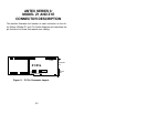
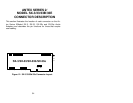
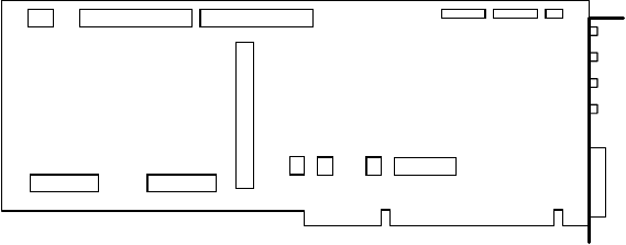
This section illustrates the location of each connector on the An-
tex Series 3/Model Z1 and Z1e Audio Adapters and describes the
pin functions for those that require user cabling.
Figure 11. Z1/Z1e Connector Layout.
J1
J13
J12
J11
J2
J3
J4
J5
OUT
CD-ROM
MIC
IN
MIC
AUX/CD-ROM
OUT
J10
JOYSTICK/
MIDI
1
1
1
Z1/Z1e
AUX/
JP4
SCSI
JP1&2
I/O IRQ
JP5&6 JP7
JOY
ENABLE
ADDR
JP3
SCSI
ENABLE
J14
(Z1e only)
(Z1 only)


