


32
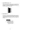
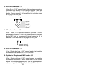
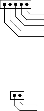
3. AUX/CD-ROM Header - J4
J4 is a 5-pin, 0.100" spaced header that provides connections
for left and right auxiliary or CD-ROM input signals. These are
the same connections provided by the AUX jack on the
bracket. Signals present at J4 are switched in only when there
is no plug in the AUX jack.
1
5
Ground
Left In
p
ut
Ri
g
ht In
p
ut
Ground
Ground
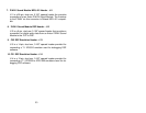
4. Microphone Header - J5
J5 is a 2-pin, 0.100" spaced header that provides a micro-
phone input connection. This is the same connection provided
by the MIC jack on the bracket. A signal present at J5 is
switched in only when there is no plug in the MIC jack.
1
Ground
MIC In
p
ut
2
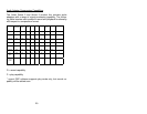
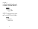
5. SCSI CD-ROM Header - J1
J1 is a 50-pin, dual-row, 0.100" spaced header that provides
connections for a standard SCSI CD-ROM drive.
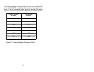
6. Synthesizer Daughtercard MIDI Header - J2
J2 is a 26-pin, dual-row, 0.100" spaced header the provides
connections for an Antex Z.WAV Sound Module or any Sound
Blaster 16 compatible daughtercard. Data is transmitted seri-
ally according to the MIDI specification, but at TTL levels.