11. KEY PAD MEMBRANE REPLACEMENT
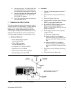
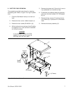
This procedure provides instructions for replacing
the key pad membrane. Refer to Figure 7 (page 7)
during this procedure.
1. Place the Site Master face up on a work sur
-
face.
2. Remove the four corner rubber bumpers (1).
3. Remove the four screws (PN 900-811) (2).
4. While holding the two halves of the Site Mas
-
ter together, turn it over and set it face down
on the work surface.
CAUTION
In the next step, the PCB Assy (3)
and test port panel (4) must stay
with the front panel.
5. Remove the bottom half (5) and fold it over to
lay upside down on the work surface.
6. Disconnect the red/black cable of the battery
pack from the main PCB assembly connector
J6 (6).
7. Remove the screw (10) located on the bottom
side of the main PCB assembly next to the
RF Bridge assembly .
8. Pull the PCB assemblies clear from the top
half of the case.
9. Lift the keypad membrane clear from the
keypad assembly.
10. Install a new membrane.
NOTE
Carefully use pliers to pull the rub
-
ber tabs tight to ensure that the
membrane is flush with the PCB.
11. Reverse the above procedure to re-assemble
the Site Master.
12. LCD REPLACEMENT
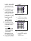
This procedure provides instructions for replacing
the Liquid Crystal Display (LCD). Refer to Figure 7
(page 7) during this procedure.
1. Place the Site Master face up on a work sur
-
face.
2. Remove the four corner rubber bumpers (1).
3. Remove the four screws (PN 900-811) (2).
4. While holding the two halves of the Site
Master together, turn it over and set it face
down on the work surface.
CAUTION
In the next step, the PCB Assy (3)
and test port panel (4) must stay
with the front panel.
5. Remove the bottom half (5) and fold it over to
lay upside down on the work surface.
6. Disconnect the red/black cable of the battery
pack from the main PCB assembly connector
J6 (6).
7. Remove the screw (10) located on the bottom
side of the main PCB assembly next to the
RF Bridge assembly .
8. Pull the PCB assemblies clear from the top
half of the case.
9. Remove the grey/brown cable of the LCD as
-
sembly from the main PCB assembly connec
-
tor J8.
10. Remove the four screws from the LCD PCB
assembly.
11. Carefully remove the 20-way ribbon cable
from the connector on the keypad PCB as
-
sembly.
12. Install the new LCD PCB assembly. Use
thread locker on the LCD mounting screws.
13. Reverse the above procedure to re-assemble
the Site Master.
Site Master S820A MM 9


