


Ampex 1308903-02 5
ATM 300 Series Switches and Indicators
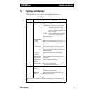
1.6 Switches and Indicators
Table 2 describes the front and rear panel switches and indicators.
Table 2. Switches and Indicators
Panel Name Description
Front DATA FLOW
(switch)
Determines how the ATM unit responds to a missing
or invalid OC-3 input.
CONTINUOUS - Continues record and playback
operations at 155.52 Mbits/sec as
determined by an internal crystal
oscillator. This provides a valid OC-3
output during playback regardless of the
OC-3 input status.
GATED - Pauses record and playback operations
until valid OC-3 input is restored.
The ATM unit resumes normal operation after the
OC-3 input is restored.
TRANSMITTER
EMPTY
(yellow
indicator)
Indicates data rate from the tape drive is too slow.
This is to be expected whenever the tape drive is not
supplying data.
FULL
(red indicator)
Indicates data rate from the tape drive is too fast. This
is an abnormal condition and most likely indicates
that the tape drive is not using its write input to
regulate its playback rate (internal playback clock*
should be disabled).
OK (green
indicator)
Indicates correct data rate from the tape drive.
RECEIVER OK
(green indicator)
Indicates ATM unit receiving valid OC-3 optical
signal input.
POWER (green
indicator)
Indicates ATM unit is powered-up.
POWER (switch) ON - Powers up the ATM unit.
OFF - Powers down the ATM unit.
Rear TEST LOOP
(switch)
TEST - Self test operation.
NORMAL - Normal operation.
ERROR (red
indicator)
Indicates (during normal operation) that a valid
HOTLink input is missing.
RESET (button) Resets the ATM unit during normal operation.
*For setting internal playback clock options, see DIS Tape Drive or ACL Installation and
Operation manual.