


©American Audio® - www.americanaudio.us - M822FX Instruction Manual Page 12
M822FX MAIN CONTROLS AND FUNCTIONS cont.
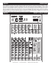
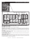
MAIN CONTROL SECTION:
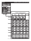
8. DSP PROGRAM DISPLAY - This displays shows the number of the selected effect. Please see the
effect list located on the MAIN CONTROL SECTION of the mixing console.
9. DSP PROGRAM SELECT KNOB - The program knob wil allow you to select one of the 100 built-in
digital effects. This control board has a 24 Bit digital high quality effect processor.
10. DSP ON/OFF BUTTON - This button turns the internal effect program on/off.
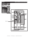
11. TAPE IN CONTROL - This knob controls the playback signal level from the component that is
connected to the TAPE IN RCA JACKS located on at the top panel of the mixing board.
12. AUX RETURN CONTROL - Use the corresponding control knobs to adjust the signal level of the
mixed L/R signal sent from the RETURN jack (L & R MONO) to the AUX bus.
13. EFX RTN KNOB - With this knob you can adjust the signal level sent from the digital effect to the
MAIN bus.
14. CTRL ROOM/PHONES KNOB - Controls the level of the signal output to the PHONES jack and
the CTRL ROOM L and R jacks.
15. POWER INDICATOR - This indicator will light when mixer power switch is turned on.
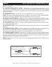
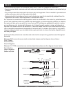
16. PHANTOM POWER BUTTON - When this button is pressed “In”, the mixer will supply power to
all channels the provide XLR MIC input jacks. Use this function when using one or more condensor
microphones.
Note: When this function is active, the mixer supplies DC +48V power to pins 2 and 3 of all XLR
type MIC input jacks.
• Leave this switch off if you do not need phantom power.
• When you turn this function on, make sure that only condenser MICs are connected to the XLR
input jacks. Devices other then condensor MICs may be damaged if connected to the phantom
power supply.
• The switch may be left on when connecting to balanced dynamic microphones.
• To avoid damage to speakers, be sure to turn off the amplier (on powered speakers) before turn-
ing this function on or off. Also, to avoid loud noises that could cause hearing loss or device dam-
age, we recommend that you turn all out controls (MAIN, master fader, etc.) to the minimum set-
tings before activating this function.
17. LEVEL METER - This LED displays the signal level of the selected LEVEL METER SIGNAL BUTTON.
When the meter lights up RED then the output is hitting the clipping level.
18. MAIN L/R KNOB - This knob adjusts the nal signal level sent to the MAIN L/R output.