


MULTI-TASKER
8
8
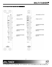
INSTALLING YOUR MT113-102/103 6
Step 1.
Slide the
MT113-102/103
into an available
slot in the Multi-Tasker™ Basic Enclosure
in order to connect to the bus. Make sure
that the
MT113-102/103
card fits into
place. Secure the card to the Multi-
Tasker™ by tightening the retainer
screws located on the top and bottom of
the
MT113-102/103
card.
Step 2.
The LED on the card panel will turn red
indicating that the card is in full operation.
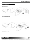
Step 3.
Connect audio cables from the audio
source to the input connector of the
MT113-102/103
. Connect the output
connectors of the
MT113-102/103
to the
audio equipment through an audio cable.
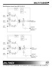
Step 4.
Starting from the left, identify the slot
number where the
MT113-102/103
card
is
plugged into the Enclosure and note that
it is for RS-232 control.
OPERATION 7
7.1 RS-232 CONTROL
When used in the Multi-Tasker™ Enclosure, the
MT113-102/103
has many advanced remote control
capabilities, which are accessible through standard
RS-232 communication. The actual controlling can
be accomplished through a computer control system
or any other device capable of sending RS-232
commands.
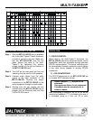
7.1.1 RS-232 INTERFACE
The RS-232 commands for the
MT113-102/103
are
in a simple ASCII character format.
1. Square brackets “[ ]” are part of the
command.
2. Use uppercase letters for all commands.
3. Commands may be executed with or
without a space.
After processing a command, an OK or ER will be
returned as feedback if "F" is included at the end of
a command string or if the unit ID is zero.