


Refer to your camcorder
manual.
Refer to section 2.2.2
above.
Refer to your camcorder
manual.
Important:
2.3 Mounting the
Receiver on a Camera
(1s)
2.4 Using the Belt Clip
2.4.1 Attaching the
Belt Clip
2.4.2 Removing the
Belt Clip
2.5 Audio Connection
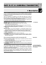
18 V DC and has a fixed 20-in. (50-cm) connecting cable with stripped and tinned
leads.
An automatic fuse switches the PA 81 OFF if the supply voltage is shorted.
The PA 81 requires a maximum power of 1 watt.
1. Check that the voltage source on your camcorder provides a voltage between
5 V DC and 18 V DC and sufficient current to satisfy the 1-watt power re-
quirement of the PA 81. Also check what type of connector you will need.
2. Fix a connector of the type matching your camcorder DC output to the
connecting cable of the supply adapter.
3. Open the battery compartment (1i).
4. Insert the supply adapter into the battery compartment (1i) so that the
connectng cable will pass through the opening in the bottom panel of the
receiver.
If you insert the supply adapter in a different orientation the receiver will not
be powered and you will not be able to close the battery compartment (1i).
5. Align the battery compartment cover (1l) with the guide grooves on the battery
compartment (1i) and push the battery compartment cover (1l) against the
direction of the arrow to the point that the battery compartment cover (1l)
clicks shut.
6. Plug the connecting cable into the appropriate jack on your camcorder.
If the automatic fuse has switched the supply adapter OFF because the
supply voltage has been shorted:
1. Unplug the connecting cable from the camcorder.
2. Correct the problem.
3. Plug the connecting cable into the camcorder jack again.
1. Remove the backing from the supplied Velcro strips.
2. Attach one of the Velcro strips to the rear panel of the receiver.
3. Attach the other Velcro strip to the camera. In order to ensure perfect re-
ception, position the Velcro strip so that the antennas (1g) on the receiver will
protrude above the camera.
You can fix the belt clip (1p) to the receiver in four different ways:
a) On the rear panel, pointing down. The antennas (1g) will be pointing up.
b) On the rear panel, pointing up. The antennas (1g) will be pointing down.
c) On the front panel, pointing down. The antennas (1g) will be pointing up.
d) On the front panel, pointing up. The antennas (1g) will be pointing down.
1. Insert the ends of the belt clip (1p) into the fixing holes in the side panels of
the receiver.
The belt clip (1p) will lock the battery compartment cover (1l).
2. Clamp the receiver to the belt or a shirt or jacket pocket.
3. Point each antenna (1g) away from the receiver at an angle of approximately
45 degrees.
Use a screwdriver as a lever to lift both ends of the belt clip (1p) out of the fixing
holes in the receiver side panels.
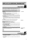
The supplied connecting cable lets you connect the line output on pin 2 of the
mini XLR jack (1r) on the receiver to an XLR input on a camcorder or mixing
console.
1. If the selected input provides phantom power, switch the phantom power OFF.
Refer to the manual of your camcorder or mixing console.
2. Plug the mini XLR connector on the connecting cable into the AUDIO OUT
jack (1r) on the receiver.
3. Plug the XLR connector on the connecting cable into the desired XLR input
jack.
23
PART II: PR 81 RECEIVER
II