5.2 Communication Setup
5.2.3 How to Set Up the Ethernet Connection
5 - 33
1
OVERVIEW
2
SYSTEM
CONFIGURATION
3
SPECIFICATIONS
4
SCREEN
CONFIGURATION
5
OPERATING
METHOD
6
FUNCTIONS
7
INTERNAL DEVICE
INTERFACE
FUNCTION
8
TROUBLESHOOTING
APPENDICES
5 When using CNC C70 (Q17nNCCPU)
For communications with GT SoftGOT1000 via the Display I/F of the CNC C70, setting items and
precautions are described below.
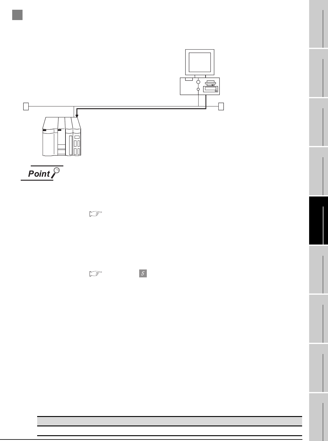
This section describes the system configuration for monitoring the host station as shown below.
Before creating Display I/F connection
(1) Display I/F connection
For the Display I/F connection, read the following manual carefully, and fully
understand the details.
C70 Setup Manual
(2) Setting items
The port No. specified for the Ethernet connection to the CNC C70 is fixed at
"5001".
Refer to the following for how to set the N/W No., IP address, and port No. of the
CNC C70 and GT SoftGOT1000.
This section (6)
The following shows the procedures for communications with the CNC C70.
(1) Before setting
(a) Precautions for monitoring
GT SoftGOT1000 cannot monitor other stations.
GT SoftGOT1000 cannot monitor CPUs on the other networks.
(b) Precautions for communication
When multiple network devices (including GT SoftGOT1000) are connected to the same
segment, the network load may increase, and the communication speed may slow down
between GT SoftGOT1000 and the PLC.
The following actions may improve the communication performance.
• Use a switching hub.
• Use the high-speed 100BASE-TX (100Mbps).
• Reduce the monitoring points of GT SoftGOT1000.
(2) Compatible models
Compatible models
Q173NCCPU
N/W No.
PC No.
IP address
Port No. : 5001
<GT SoftGOT1000>
: 1
: 3
: 192.168.0.18
N/W No.
PC No.
IP address
Port No. : 5001
: 1
: 2
: 192.168.0.19
<Q17nNC> Host
