5.2 Communication Setup
5.2.3 How to Set Up the Ethernet Connection
5 - 29
1
OVERVIEW
2
SYSTEM
CONFIGURATION
3
SPECIFICATIONS
4
SCREEN
CONFIGURATION
5
OPERATING
METHOD
6
FUNCTIONS
7
INTERNAL DEVICE
INTERFACE
FUNCTION
8
TROUBLESHOOTING
APPENDICES
(3) E71 switch settings
(4) Sequence programs
Initial processing and communication line open processing sequence programs are needed.
Necessary communication parameters and sequence program examples are given below.
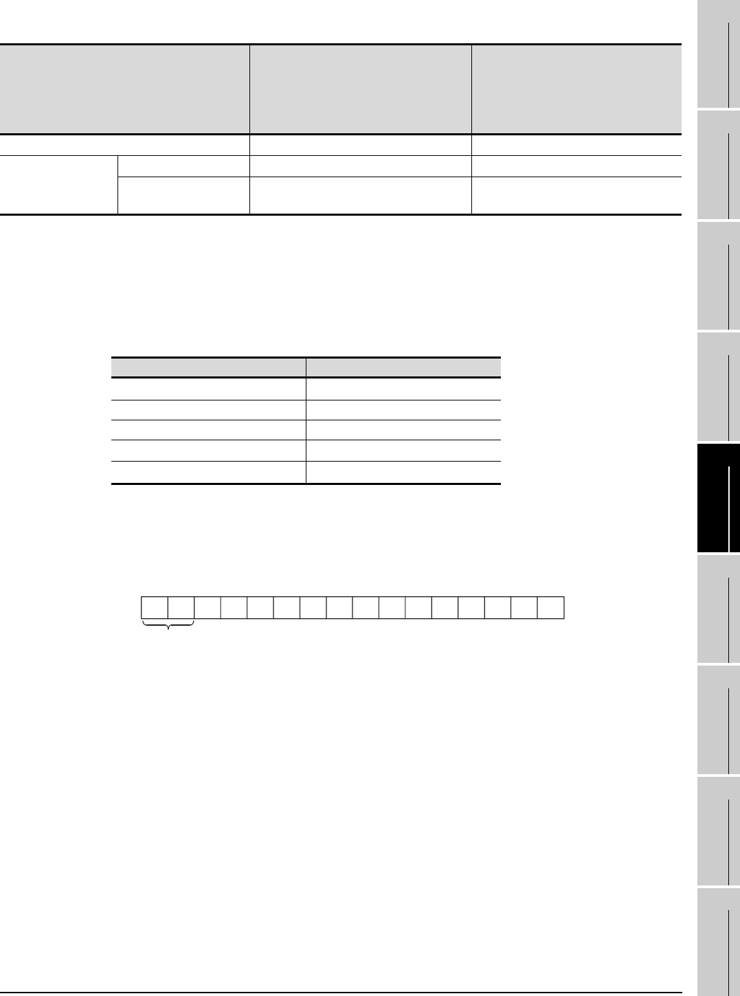
(a) Communication parameters
The following are the communication parameter setting examples for the host side.
*1 Value specified for application setting
The user can change the settings of 1), 2) and 3).
4), 5) and 6) are fixed settings.
The following shows details of the application setting.
1): Fixed buffer application
0: For send/no communication
1: For receive
2): Existence check
0: No
1: Yes
3): Paring open
0: No
1: Yes
4): Communication system (Set to 1: UDP/IP)
5): Fixed buffer communication (Set to 0: With procedure)
0: With procedure
1: Without procedure
6): Open system (Set to 00: Active, UDP/IP)
*2: The other node port number is a fixed setting.
The user can change the other settings.
Switch
AJ71E71N3-T, AJ71E71N-B5,
AJ71E71N-B2, AJ71E71N-T,
AJ71E71N-B5T, AJ71E71-S3,
A1SJ71E71N3-T, A1SJ71E71N-B5,
A1SJ71E71N-B2, A1SJ71E71N-T,
A1SJ71E71N-B5T
A1SJ71E71-B2-S3, A1SJ71E71-B5-S3
Operation mode setting switch O (Online mode) O (Online mode)
Exchange condition
setting switch
Data code setting SW2 OFF (Binary code) SW2 OFF (Binary code)
CPU exchange timing
setting
SW7 ON (Online change enabled) SW3 ON (Online change enabled)
Setting item Set value
Application setting
*1
100
H
IP address of E71 192.168.0.2
E71 port number 5001
IP address of other node
FFFFFFFF
H
Other node port number
*2
FFFF
H
b12b15 b14 b13 b11 b10 b9 b8 b7 b6 b5 b4 b3 b2 b1 b0
0000000100000000
5)
6)
1)
2)
3)
4)
