


10
CONTROLS AND FUNCTIONS
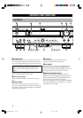
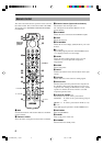
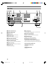
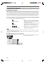
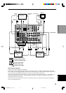
Rear Panel
1 DIGITAL OUTPUT jacks
2 DIGITAL INPUT jacks
3 GND terminal
See page 12 for connection information.
4 6CH INPUT jacks
See page 13 for connection information.
5 Antenna input terminals
See page 29 for connection information.
6 Video component jacks
See pages 14 and 15 for connection information.
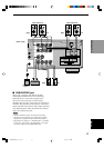
7 Speaker terminals
See pages 16 and 17 for connection information.
8 AC power cord
Connect to a power outlet.
9 AC OUTLET(S)
Use these outlets to supply power to your other audio/
video components (see page 18).
0 Audio component jacks
See pages 12 and 13 for connection information.
q SUBWOOFER jack
See page 17 for connection information.
w IMPEDANCE SELECTOR switch
Use this switch to match the amplifier output to your
speaker impedance. Set this unit in the standby mode
before you change the setting of this switch (see page 18).
China and General models only
FREQUENCY STEP switch
See page 29.
VOLTAGE SELECTOR
See page 18.
1
2
4 5
6 7
8 9
q w
0
3
SWITCHED
100W MAX.
TOTAL
SPEAKERS
MAIN
+ –
R L
A
– +
B
CENTER
+ –
REAR
(SURROUND)
R
L
+ ––+
DVD
MONITOR
OUT
D-TV/CBL
YPB/CB PR/CR COMPONENT VIDEO
S VIDEO
VIDEO
MONITOR OUT
DVD
DVD
DVD
D-TV/CBL
D-TV/CBL
D-TV/CBL
IN
VCR 1
OUT IN
VCR 2
/DVR
OUT
VIDEO SIGNAL
AUDIO SIGNAL
SUB
WOOFER
OUTPUT
IN
VCR 1
OUT IN
VCR 2/DVR
OUT
OUT(REC)
IN(PLAY)
CD
PHONO
MD/CD-R
MD/CD-R
MD/CD-R
R
L
DIGITAL
OUTPUT
OPTICAL
OPTICAL
COAXIAL
AM ANT GND
FM ANT
75
UNBAL.
TUNER
GND
MAIN
CENTER
SUB WOOFER
SURROUND
DIGITAL
INPUT
6CH INPUT
CD
R
L
R
L
AC OUTLETS
IMPEDANCE SELECTOR
SET BEFORE POWER ON
MAIN A OR B: 4
MIN. /SPEAKER
A
+
B: 8
MIN. /SPEAKER
CENTER
: 6
MIN. /SPEAKER
REAR
: 6
MIN. /SPEAKER
MAIN A OR B: 8
MIN. /SPEAKER
A
+
B:
16
MIN. /SPEAKER
CENTER
: 8
MIN. /SPEAKER
REAR
: 8
MIN. /SPEAKER
(U.S.A. model)
0102V620(UCA)_1-10_EN 1/16/1, 11:19 AM10