


6
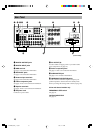
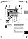
CONTROLS AND FUNCTIONS
A/B/C/D/E
TV INPUT
TV VOLUME
TV POWER
EFFECT
e
r
1
2
3
4
5
6
7
9
8
q
w
0
t
y
u
i
o
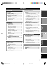
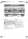
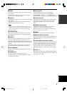
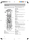
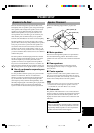
Remote Control
This section describes the basic operation of this unit with
the remote control. First, set the selector dial to the AMP/
TUN position. See “REMOTE CONTROL FEATURES”
for full details.
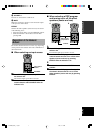
Select the
AMP/TUN
position.
1 DSP
Switches the function of the numeric buttons to the DSP
program selector.
2 Indicator window
Shows the name of components which can be controlled.
3 Numeric buttons (Input selector buttons)
These buttons select the input source.
See “Description of the Numeric Buttons” for the
numeric buttons.
4 6CH INPUT
Selects the source connected to the 6CH INPUT jacks.
5 TEST
Outputs the test tone.
6 ON SCREEN
Selects the on-screen display (OSD) mode for your video
monitor.
7 j / i (–/+)
Adjust DSP program parameters and SET MENU items.
–/+ is displayed on the on-screen display.
8 LEVEL
Selects the effect speaker channel (center, rear and
subwoofer) so you can adjust their output level
independently.
9 SLEEP
Sets the sleep timer.
0 INPUT
Switches the function of the numeric buttons to the input
selector.
q Indicator
Flashes while the remote control is sending signals.
w Selector dial
Turn this dial to select the position for the component to
be controlled. (The proper code must be set up for your
component. See “Setting the Manufacture Codes”.) When
a position is selected, the remote control is set to that
component operation mode.
e A/B/C/D/E, PRESET –/+
These buttons are used to select a preset station.
A/B/C/D/E: To select one of 5 preset station groups (A
to E)
PRESET –/+: To select a preset station number (1 to 8)
r u/d
Select DSP program parameters and SET MENU items.
t SET MENU
Enters the SET MENU.
y POWER
Turns on the power of this unit.
u STANDBY
Sets this unit in the standby mode.
0102V620(UCA)_1-10_EN 1/16/1, 11:19 AM6