


12
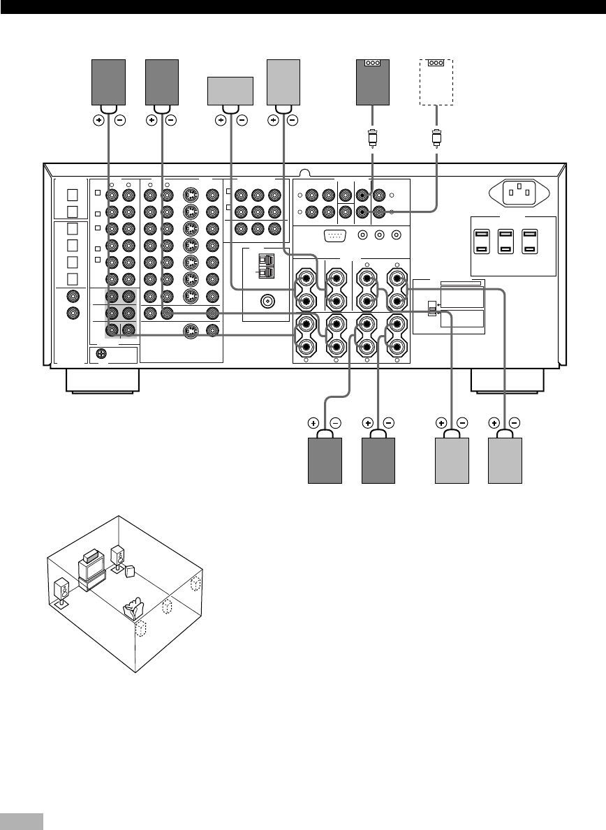
SPEAKER SETUP
75Ω UNBAL.
AM
ANT
TUNER
COMPONENT VIDEO
IMPEDANCE SELECTOR
SET BEFORE POWER ON
REAR :
REAR CENTER :
CENTER
:
MAIN A OR B
:
A B :
REAR :
REAR CENTER :
CENTER
:
MAIN A OR B
:
AC OUTLETS
PRE OUT/MAIN IN
MAIN OUT
Y
P
R
/C
R
P
B
/C
B
DVD
MONITOR
OUT
DVD
IN
VCR 1
OUT
IN
VCR 2
/DVR
OUT
ZONE 2 OUT
S VIDEO VIDEO
D-TV
/LD
CBL
/SAT
D-TV
/LD
MAIN IN
REAR (SURROUND)
SUB
WOOFER
CENTER
IN OUT
SPEAKERS
REARCENTER
MAIN
+
+
–
+
–
+
–
–
+
–
REAR
CENTER
REMOTE
RS-232C
CONTROL
OUT
+12V
10mA MAX.
(SURROUND)
REAR
CENTER
VIDEO
VIDEOS VIDEO
AUDIO
DIGITAL INPUT
GND
6CH INPUT
CENTER
MAIN
SURROUND
AUDIODIGITAL OUTPUT
GND
MONITOR
OUT
PHONO
CBL
/SAT
CD
D-TV
/LD
DVD
CD-R
CD-R
MD/
TAPE
CD
OPTICAL
COAXIAL
SUB
WOOFER
CD
OUT (REC)
CD-R
IN (PLAY)
OUT (REC)
MD/TAPE
IN (PLAY)
FM
ANT
R
L
R
L
R
L
R
L
R
L
R
L
R
L
AB
+
4ΩMIN. /SPEAKER
4ΩMIN. /SPEAKER
4ΩMIN. /SPEAKER
4ΩMIN. /SPEAKER
8ΩMIN. /SPEAKER
8ΩMIN. /SPEAKER
8ΩMIN. /SPEAKER
8ΩMIN. /SPEAKER
8ΩMIN. /SPEAKER
1
2
3
4
5
6
7
8
3
A
B
4
3
4
1
1
45 6 7
23
SWITCHED
100W MAX. TOTAL
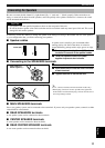
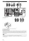
Subwoofer
system
Rear Center
speaker
Main B speaker
Center
speaker
(U.S.A. model)
Right
Rear speaker
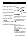
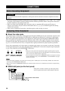
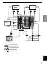
■ SUBWOOFER jack
When using a subwoofer with built-in amplifier, including the YAMAHA Active Servo Processing Subwoofer System,
connect the input jack of the subwoofer system to this jack. Low bass signals distributed from the main, center and/or
rear channels are directed to this jack if they are assigned to this jack. (The cut-off frequency of this jack is 90 Hz.) The
LFE (low-frequency effect) signals generated when Dolby Digital or DTS is decoded are also directed if they are
assigned to this jack.
Notes
• Adjust the volume level of the subwoofer with the control on the subwoofer. It is also possible to adjust the volume level by using the
remote control of this unit (see ADJUSTING THE LEVEL OF THE EFFECT SPEAKERS on page 67).
• Depending on the settings of “1 SPEAKER SET” and “10 LFE LEVEL” on the SET MENU, some signals may not be output from
the SUBWOOFER jack.
Right Left
Main A speaker
Right Left
Left
4
5
3
1
2
7
6
The diagram above shows the speaker layout in the listening room.