


5
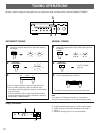
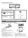
ABOUT THE ACCESSORY TERMINALS
AC OUTLET(S) (SWITCHED)
(U.S.A., Canada and General models)
...........................................................2 SWITCHED OUTLETS
(Australia model) ................................. 1 SWITCHED OUTLET
Use these to connect the power cords from your components
to this unit.
The power to the SWITCHED outlets is controlled by this unit’s
POWER switch or the provided remote control transmitter’s
POWER key. These outlets will supply power to any
component whenever this unit is turned on.
The maximum power (total power consumption of
components) that can be connected to the SWITCHED AC
OUTLET(S) is 100 watts.
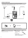
GND terminal (For turntable use)
Connecting the ground wire of the turntable to this terminal will
normally minimize hum, but in some cases better results may
be obtained with the ground wire disconnected.
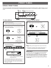
For Custom Installer
REMOTE CONTROL (IN, OUT) terminals
(U.S.A. and Canada models only)
These terminals are used for custom installation system.
When this unit is connected to the components for custom
installation system, you can operate this unit with the
system remote control.
Connect the REMOTE CONTROL IN terminal to the
EMITTER terminal (FROM INDEPENDENT ZONE, FROM
ALL ZONE or FROM SELECTED ZONE) of the YAMAHA
Master Zone Controller MCX-10.
By connecting the REMOTE CONTROL OUT terminal to
the REMOTE CONTROL IN terminal of the other
component, you can also operate it with the system remote
control. In this way, up to 6 components can be connected
in series.
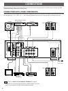
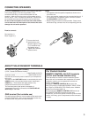
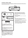
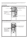
Connect the SPEAKERS terminals to your speakers with wire
of the proper gauge, cut as short as possible. If the
connections are faulty, no sound will be heard from the
speakers. Make sure that the polarity of the speaker wires is
correct, that is, + and – markings are observed. If these wires
are reversed, the sound will be unnatural and will lack bass.
Do not let the bare speaker wires touch each other and do
not let them touch the metal parts of this unit as this could
damage this unit and/or speakers.
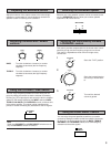
How to connect:
Red: positive (+)
Black: negative (–)
➀
Unscrew the knob.
➁
Insert the bare wire.
[Remove approx. 5mm
(1/4”) insulation from
the speaker wires.]
➂
Tighten the knob and
secure the wire.
Notes
• Use speakers with the specified impedance shown on the
rear of this unit.
• One or two speaker systems can be connected to this unit. If
you connect only one speaker system, connect it to either
the SPEAKERS A or B terminals.
• Banana Plug connections are also possible. Simply insert
the Banana Plug connector into the corresponding terminal.
1
2
3
CONNECTING SPEAKERS