


4
CONNECTIONS
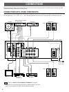
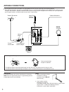
Before attempting to make any connections to or from this unit, be sure to first switch OFF the power to this unit and to any other
components to which connections are being made.
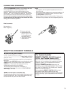
CONNECTIONS WITH OTHER COMPONENTS
When making connections between this unit and other components, be sure all connections are made correctly, that is to say L (left)
to L, R (right) to R, “+” to “+” and “–” to “–”. Also, refer to the owner’s manual for each component to be connected to this unit.
: Refer to “ABOUT THE ACCESSORY TERMINALS” on page 5.
* If a tape deck is connected to the VCR/TAPE 2 (AUDIO SIGNAL) terminals,
there is no connection to the VCR (VIDEO SIGNAL) terminals.
PHONO
A OR B : 6ΩMIN./SPEAKER
A B : l2ΩMIN./SPEAKER
AUDIO SIGNAL
SPEAKERS
A
B
GND
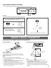
REMOTE
CONTROL
CD
TAPE 1
TAPE
PB
REC
OUT
VCR /
TAPE 2
TAPE
PB
REC
OUT
LD/
TV
IN
VCR
OUT
LD/
TV
MONITOR
OUT
VIDEO SIGNAL
AUDIO
SIGNAL
IN
OUT
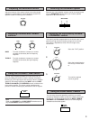
FREQUENCY
STEP
50 kHz
l00 kHz
9 kHz
l0 kHz
FM AM
FM
ANT
AM
ANT
GND
l20V 60Hz
l00W MAX. TOTAL
AC OUTLETS
SWITCHED
75Ω
UNBAL.
OUTPUT
GND
LINE OUT
LINE IN
VIDEO IN
AUDIO OUT
VIDEO OUT
VIDEO OUT
AUDIO OUT
VIDEO IN
AUDIO IN
OUTPUT
(U.S.A. model)
To AC outlet
Turntable
Monitor TV
LD player,
TV tuner, etc.
CD player
Speakers A
Speakers B
Right
Left
Right
Left
Tape deck 1
Video cassette recorder
or Tape deck 2