


2
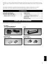
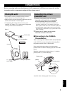
1 Antenna
Adjust the antenna direction for best signal
transmission.
2 POWER indicator
Lights red when you connect the AC adaptor to the DC
IN jack on this unit and to an AC outlet. If the unit does
not receive a signal from the amplifier within 5 minutes
after connection to the AC outlet, it places itself in
standby mode and the power indicator goes out. The
unit turns on again when it receives a signal from the
amplifier.
3 Speaker terminal cable
Connect to the surround speaker jack on your amplifier.
4 CHANNEL SELECTOR switch
Set to the number selected on the channel selector of
the wireless receiver unit (see page 5).
5 DC IN jack
Connect to the included AC adaptor.
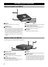
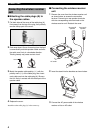
The following figure depicts the unit with the cover removed.
1 AC power cable
Connect the plug to an AC outlet.
2 Surround speaker terminal
Connect the speaker cables to the surround sound
speakers.
3 CHANNEL SELECTOR switch
Set to the number selected on the channel selector of
the wireless transmitter unit (see page 5).
4 Antenna
Adjust the antenna direction for best signal reception.
5 POWER indicator
Lights red when you connect the AC power cable to an
AC outlet. Lights green when the unit receiving a signal
from wireless transmitter unit. When the signal from
the wireless transmitter unit is cut, the unit places itself
in standby mode, and the power indicator lights red.
CONTROLS AND FUNCTIONS
Wireless transmitter unit (TRX-1T)
5
4
1
2
3
Wireless receiver unit (TRX-1R)
3
5
1
4
2