


16
CONNECTIONS
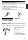
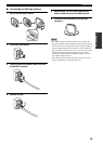
Plug the power cable into the AC IN on the rear panel of
this unit and then plug the power supply cord into the AC
wall outlet after all other connections are complete.
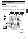
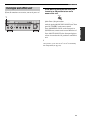
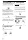
■ COUPLER jacks
Removing the jumper pins from the PRE OUT/MAIN IN
jacks enables this unit to operate separately as a control
amplifier or a power amplifier. These jacks are used to
connect a signal-processing system such as a graphic
equalizer or a surround-sound processor to this unit. If
such an external unit is connected to these jacks, the
VOLUME control of this unit can be used to adjust the
overall sound output level.
To connect an external unit, first remove the jumper pins
from the PRE OUT/MAIN IN jacks and then connect the
input jacks of that external unit to the PRE OUT jacks or
its output jacks to the MAIN IN jacks. For details, refer to
the owner’s manual included with the external unit to be
connected.
• When you do not use the COUPLER jacks, never remove the
jumper pins from these jacks. If removed, no sound will be
output from this unit.
• When you use this unit with an external unit connected to the
COUPLER jacks, make sure that the CD DIRECT AMP button
and the PURE DIRECT button on the front panel are turned off.
• When you use this unit as a power amplifier, connect the output
jacks of an external control amplifier, etc. to the MAIN IN jacks
of this unit. In this case, the controls of this unit will not
function except the PHONES jack and the SPEAKERS A/B
buttons. Use the controls on the external control amplifier to
make volume adjustments, etc.
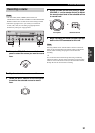
■ AC OUTLET(S) (SWITCHED)
Australia model ......................................................1 outlet
Other models ....................................................... 2 outlets
Use these outlets to connect the power supply cords from
your other components to this unit. The outlets supply
power to any connected components whenever the power
of this unit is turned on. For information on the maximum
power (total power consumption of components), see
“SPECIFICATIONS” on page 49.
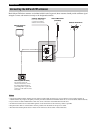
■ VOLTAGE SELECTOR
(Asia and General models only)
VOLTAGE SELECTOR on the rear panel of this unit must
be set for your local main voltage BEFORE plugging the
power supply cord into the AC wall outlet.
Voltages are as follows:
Asia model......................... AC 220/230–240 V, 50/60 Hz
General model...... AC 110/120/220/230–240 V, 50/60 Hz
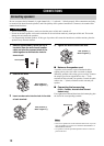
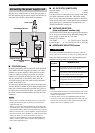
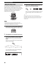
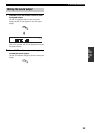
■ IMPEDANCE SELECTOR switch
Do not slide the IMPEDANCE SELECTOR switch while the
power of this unit is turned on, as doing so may damage the unit.
Select the switch position (left or right) according to the
impedance of the speakers in your system.
• The Canada model cannot use two separate speaker sets (A and
B) simultaneously when the IMPEDANCE SELECTOR switch
is slid to the 6
Ω position.
• If this unit fails to turn on, the IMPEDANCE SELECTOR
switch may not be fully slid to either position. If this is the case,
slide the switch all the way to either position when the power
supply to this unit is completely cut off.
Connecting the power supply cord
Notes
AC OUTLETS
SWITCHED
IMPEDANCE SELECTOR
SET BEFORE POWER ON
SELECTEUR D'IMPEDANCE
AC IN
A OR B: 4ΩMIN. /SPEAKER
A+B: 8ΩMIN. /SPEAKER
A OR B: 6ΩMIN. /SPEAKER
VOLTAGE
SELECTOR
(General model)
IMPEDANCE SELECTOR
switch
Power cable
VOLTAGE SELECTOR
AC OUTLET(S)
Switch
position
Impedance level
Right
If you use one set (A or B), the impedance of
each speaker must be 6
Ω or higher.
If you use two sets (A and B), the impedance
of each speaker must be 12
Ω or higher.
Left
If you use one set (A or B), the impedance of
each speaker must be 4
Ω or higher.
If you use two sets (A and B), the impedance
of each speaker must be 8
Ω or higher.
Notes
CAUTION