


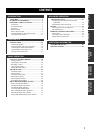
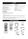
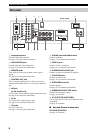
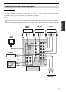

CONTROLS AND FUNCTIONS
6
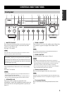
1 Antenna terminals
Connect FM and AM antennas.
See page 14 for connections information.
2 AUDIO/VIDEO jacks
Connect audio and video components.
See page 13 for connection information.
3 REMOTE jacks
These jacks are used to input/output remote control
signals.
See page 41 for connection information.
4 CONTROL OUT jack
This is a control expansion jack. Consult your nearest
authorized YAMAHA dealer or service center about this
jack.
5 XM jack
(U.S.A. model only)
Connect XM Connect-and-Play digital antenna accessory.
See page 30 for connection information.
6 AC IN
Use to plug in the supplied power cable.
See page 16 for connection information.
7 CD jacks
Connect a CD player.
See page 13 for connection information.
8 PHONO jacks and GND terminal
Connect a turntable.
See page 13 for connection information.
9 ZONE 2 jacks
Connect a Zone 2 component.
See page 41 for connection information.
0 SUBWOOFER OUTPUT jack
Connect a subwoofer with built-in amplifier.
A COUPLER jacks
Connect an external unit.
See page 16 for connection information.
B SPEAKERS terminals
Connect speakers.
See page 12 for connection information.
C IMPEDANCE SELECTOR switch
Switches the impedance setting.
See page 16 for details.
D AC OUTLET(S) (SWITCHED)
Use to supply power to your other audio and video
components.
See page 16 for details.
■ Asia and General models only
VOLTAGE SELECTOR
See page 16 for details.
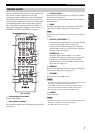
Rear panel
AC OUTLETS
SWITCHED
IMPEDANCE SELECTOR
SET BEFORE POWER ON
SELECTEUR D'IMPEDANCE
SPEAKERS
CLASS 2 WIRING
A
B
AC IN
XMREMOTE
OUT
IN
DVD
DTV/
CBL
IN
IN
(PLAY)
OUT
(REC)
OUT
MD/
TAP E
ZONE 2
OUT
ZONE 2
OUT
MONITOR
OUT
VCR
DVD
GND
GND
AM
ANT
FM
ANT
75Ω
UNBAL.
DTV/
CBL
IN
OUT
CD
PHONO
VCR
IN
MAIN
IN
PRE
OUT
SUB
WOOFER
+12V 15mA MAX.
2
1
CONTROL OUT
COUPLER
OUTPUTAUDIOAUDIO
VIDEO
TUNER
A OR B: 4ΩMIN. /SPEAKER
A+B: 8ΩMIN. /SPEAKER
A OR B: 6ΩMIN. /SPEAKER
70 CD8AB
1235 6
4
9
(U.S.A. model)