


13
CONNECTIONS
PREPARATION
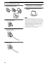
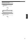
Plug the power supply cord into the AC wall outlet after
all other connections are complete.
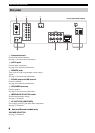
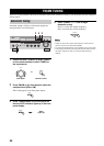
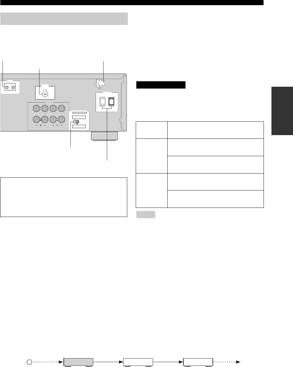
■ AC OUTLET(S) (SWITCHED)
Australia model ......................................................1 outlet
Other models ....................................................... 2 outlets
Use these outlets to connect the power supply cords from
your other components to this unit. The AC OUTLET(S)
supplies power to any connected components whenever
the power of this unit is turned on. For information on the
maximum power (total power consumption of
components), see “SPECIFICATIONS” on page 30.
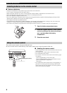
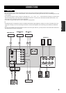
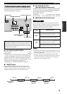
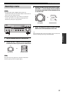
■ REMOTE jacks
Some YAMAHA models are able to connect directly to the
REMOTE jack on the rear panel of this unit. If you own these
products, you may not need to use an infrared emitter. Up to six
YAMAHA components can be connected as shown below.
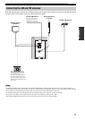
■ VOLTAGE SELECTOR
(Asia and General models only)
VOLTAGE SELECTOR on the rear panel of this unit must
be set for your local main voltage BEFORE plugging the
power supply cord into the AC wall outlet.
Voltages are as follows:
Asia model ......................... AC 220/230–240 V, 50/60 Hz
General model...... AC 110/120/220/230–240 V, 50/60 Hz
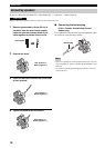
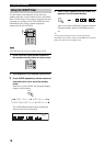
■ IMPEDANCE SELECTOR switch
Do not slide the IMPEDANCE SELECTOR switch while the
power of this unit is turned on, as doing so may damage the unit.
Select the switch position (left or right) according to the
impedance of the speakers in your system.
• The Canada model cannot use two separate speaker sets (A and
B) simultaneously when the IMPEDANCE SELECTOR switch
is slid to the right position.
• If this unit fails to turn on, the IMPEDANCE SELECTOR
switch may not be fully slid to either position. If this is the case,
slide the switch all the way to either position when the power
supply to this unit is completely cut off.
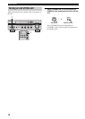
Connecting the power supply cord
Memory back-up
The memory back-up circuit prevents the stored data
from being lost. However, the stored data will be lost if
the power cord is disconnected from the AC wall outlet
for more than one week.
REMOTE
IN OUT
A OR B: 4ΩMIN. /SPEAKER
A + B: 8ΩMIN. /SPEAKER
A OR B: 8ΩMIN. /SPEAKER
A + B:16ΩMIN. /SPEAKER
IMPEDANCE SELECTOR
SET BEFORE POWER ON
SPEAKERS
CLASS 2 WIRING
VO LTAGE
SELECTOR
A
B
AC OUTLETS
SWITCHED
(General model)
IMPEDANCE SELECTOR
switch
AC power supply cord
VOLTAGE SELECTOR
AC OUTLET(S)
REMOTE jacks
Switch
position
Impedance level
Right
If you use one set (A or B), the impedance of
each speaker must be 8
Ω or higher.
If you use two sets (A and B), the impedance
of each speaker must be 16
Ω or higher.
Left
If you use one set (A or B), the impedance of
each speaker must be 4
Ω or higher.
If you use two sets (A and B), the impedance
of each speaker must be 8
Ω or higher.
Notes
CAUTION
OUTOUT
IN
REMOTE
IN
REMOTE
OUT
IN
REMOTE
REMOTE
This unit
YAMAHA
component
YAMAHA
component
Infrared signal
receiver