


6
Controls and Functions
■
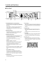
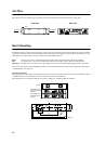
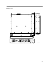
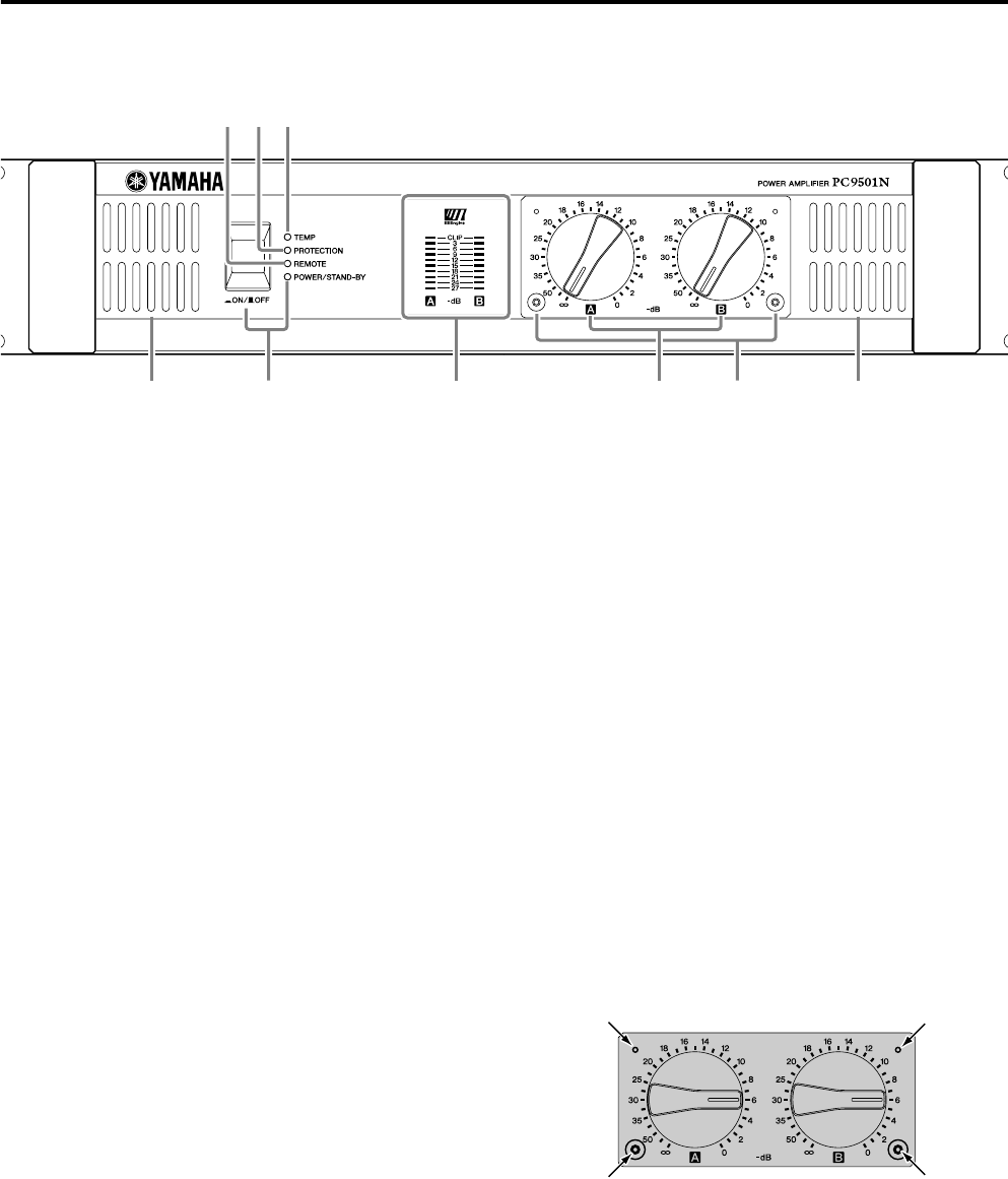
Front Panel
1
POWER/STAND-BY switch and indicator
This turns the power of the amplifier on/off. When you
press the switch to turn on the power, the indicator will
light green.
If the amplifier is connected to an amp control device
ACD1 or ACU16-C and the amplifier has been
commanded to enter STAND-BY mode, this indicator
will light orange.
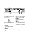
2
REMOTE indicator
This indicator will light green if the amplifier is being
controlled from an external device connected to the
DATA port located on the rear panel.
3
PROTECTION indicator
This indicator lights up red when the protection circuit
is operating. During this time, the amp will be
disconnected from the speaker system, and no sound
will be output from the speaker.
The protection system activates in the following
situations:
• When the amplifier is turned on
The protection system activates for approximately ten
seconds when the amplifier is turned on. After ten
seconds, the protection system deactivates
automatically and the amplifier is ready for normal
operation.
• If a DC voltage is detected at the amplifier’s outputs
Turn off the power, and then turn the power back on
again.
• If the amplifier overheats
When this occurs, the TEMP indicator will be lit.
You should turn off the amplifier and allow it time to
cool down. See the Precautions section of this Owner’s
Manual for ways to prevent the amplifier overheating.
4
TEMP indicator
This indicator will light red if the heat sink temperature
exceeds 85 degrees Celsius.
5
Level meters
These are nine-segment level meters that indicate the
output level of output jacks A and B. If the distortion of
the output signal exceeds 1%, the red CLIP indicator
will light.
6
Volume knobs
These are detented volume knobs that attenuate the
input signals of channels A and B over a range of –
∞
– 0 dB.
In BRIDGE mode, only the channel A knob is used.
7
Air intakes
The amplifier has a forced-air cooling fan that takes in
air from the front and exhausts it from the rear. You
must make sure that these intakes are not obstructed.
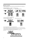
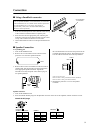
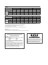
8
Security cover
If you want to keep the volume settings from being
modified, attach the included security cover using the
screw holes shown below, so that the volume controls
are inaccessible.
1 8
234
5 776