


OPERATION
9
USING THE
MCX-CA15
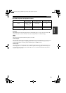
■ Mode comparison and operation outline
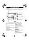
The various functions of each jack are as follows:
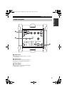
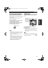
IR output
The IR/CTRL jack on the front panel functions as an IR output jack in “A” mode. You can connect an IR
flasher to this jack to control a YAMAHA AV receiver using YAMAHA AV link technology.
This unit only supports IR modulation frequencies of 38 kHz.
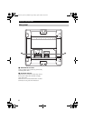
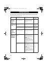
Control output
The CONTROL IN/OUT jack on the bottom panel functions as a control output jack in “A” and “B” modes.
In this case, this unit is capable of outputting power within the range 3 to 30 V from this jack. You can
connect another MCX-CA15 to this jack to control the power of that MCX-CA15.
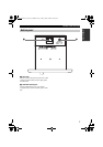
Control input
The IR/CTRL jack on the front panel and the CONTROL IN/OUT jack on the bottom panel function as a
control input jack in “C” mode. In this case, this unit is capable of detecting signals within the range 3 to
30 V from these jacks. You can connect another MCX-CA15 or an external component to these jacks to
control the power of this unit.
Mode
IR/CTRL jack on
the front panel
CONTROL IN/OUT jack
on the bottom panel
Auto standby with
input level sensing
A mode
IR output (using
YAMAHA AV link
technology)
Control output No
B mode (Not available) Control output Yes
C mode Control input Control input No
Note
00_MCX-CA15_Owners_UB.book Page 9 Friday, April 30, 2004 10:53 AM