


E-10
DVD/LD D–TV CBL/SAT VCR
R
VIDEO SIGNAL
DVD/LD D–TV CBL/SAT
IN
VCR
OUT MONITOR
OUT
VIDEO IN
VV
VIDEO
IN
VIDEO
OUT
V
VIDEO
OUT
V
V
VIDEO OUT
V
V
VIDEO
OUT
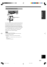
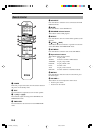
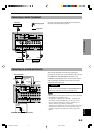
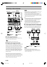
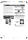
Connecting a Video Component
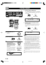
CONNECTIONS
Analog signal
Digital signal
(optical)
Digital signal
(coaxial)
Signal flow
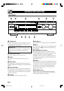
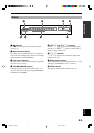
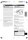
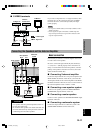
■ Audio signal terminals
Be sure to connect the right channel (R), left channel (L),
input (IN) and output (OUT) properly.
Note
• Be sure to make the video connections as well.
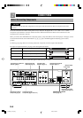
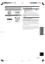
■ Digital audio signal terminals
If your DVD/LD player, TV/digital TV or cable TV/satellite
tuner, etc. has coaxial or optical digital signal output
terminals, they can be connected to this unit’s COAXIAL
and/or OPTICAL digital signal input terminals. To make a
connection between the optical digital signal terminals,
remove the cover from each terminal, and then connect
them by using a commercially available optical fiber cable
that conforms to EIA standards. Other cables might not
function correctly.
When making connections between the digital signal
terminals, you should connect the components to the same-
named analog audio signal terminals of this unit, because a
digital signal cannot be recorded by a tape deck, MD
recorder or VCR connected to this unit.
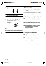
Notes
• Be sure to attach the covers when the OPTICAL terminals are not
being used in order to protect them from dust.
• If your LD player has a Dolby Digital RF signal output terminal,
be sure to use the RF demodulator (separately purchased).
• No sound will be heard when connecting your LD player’s Dolby
Digital RF signal output terminal directly to this unit’s COAXIAL
DVD/LD digital signal input terminal.
y
• The input signal from the DVD/LD or CBL/SAT input terminals
is selected in the following order of priority with the input mode
set to AUTO: COAXIAL terminal → OPTICAL terminal →
Analog terminal. Refer to page 18 for details.
• All digital signal input terminals are applicable to sampling
frequencies of 32 kHz, 44.1 kHz, 48 kHz and 96 kHz. (Refer to
page 19 about 96-kHz sampling 24-bit digital signals.)
■ Video signal terminals (composite)
If your video components do not have “S” video terminals,
they can be connected to this unit’s VIDEO terminals. Be
sure to connect the input (IN) and output (OUT) properly.
Notes
• Be sure to make the audio connections as well.
• If video signals are input from both the S VIDEO input and
composite input terminals, the signals will be directed to their
respective output terminals.
IN
R
L
MAIN
SURROUND
CENTER
SUB
WOOFER
DIGITAL SIGNAL
DVD/LD D–TV CBL/SAT
DVD/LD CBL/SAT
OPTICAL COAXIAL
AUDIO SIGNAL
1 2 3 4
CD TUNER
TAPE/MD
IN (PLAY)
OUT (REC)
DVD/LD D–TV CBL/SAT
IN
VCR
OUT
R
L
R
L
AUDIO
OUT
AUDIO
IN
DIGITAL
SIGNAL
(COAXIAL)
ANALOG
AUDIO
OUT
ANALOG
AUDIO
OUT
DIGITAL
SIGNAL
(OPTICAL)
O
DIGITAL
SIGNAL
(OPTICAL)
DIGITAL
SIGNAL
(OPTICAL)
O
DIGITAL SIGNAL
(COAXIAL)
L R
C
C
L R
L RL R
ANALOG
AUDIO OUT
L R
O
VCR
DVD/LD player
Cable TV/
satellite tuner
TV/Digital TV
L
R
C
O
Video signal
DVD/LD player
TV/Digital TV
TV monitor
VCR
Cable TV/
satellite tuner
Signal flow
103.E800_07-15(Eng) 5/18/0, 1:36 PM10