


5
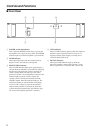
Caution for Speaker Connection
1. Turn off the POWER switch.
2. Remove the cover attachment screw(s) and remove
the protective cover from the speaker terminals.
Screw
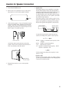
3. After removing approx. 15 mm of insulation from the
ends of the speaker cables, bind the bare ends of the
speaker wires in the corresponding speaker terminals
and tighten the terminals to securely clamp the wires.
Refer to page 3 for speaker porality.
15mm*
* Shown actual size.
At this time make sure that the bare ends of the
speaker cables do not extend from the terminals in
such a way that they touch the chassis.
Wire should not
touch the chassis.
4. Reattach the protective cover over the speaker
terminals.
• Speaker fuse
The output capacity of your amplifier is very high:
460 W+460 W (8Ω) in stereo and 1240 W (8Ω) in
monaural on the C450; 340 W+340 W (8Ω) in stereo
and 880 W (8Ω) in monaural on the C320; 160
W+160 W (8Ω) in stereo and 400 W (8Ω) in monau-
ral on the C160. Be sure to use a speaker system that
has sufficient input capacity.
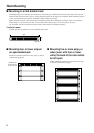
If the input capacity of your speaker system is lower
than the rated output of the power amplifier, you can
protect your speakers by connecting a fuse serially
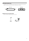
between the speaker and amplifier as shown below.
_
+ _
+
Power amplifier
Speaker system
Fuse
Use the following formula to determine the fuse
capacity according to the speaker’s input capacity.
Po = I R → I = Po/R
2
P0 [W] : Speaker’s continuous input capacity (noise
or RMS)
R [Ω] : Speaker’s nominal impedance
I [A] : Required fuse capacity
ex.) Speaker’s continuous input capacity : 100 W
Speaker’s impedance : 8Ω
I = 100/8
In this example, the required fuse capacity is calcu-
lated as 3.5 [A].
• Speaker cable
If you use a long speaker cable, use as thick a cable as
possible to prevent deterioration of the damping factor
or power loss inside the cable.