


3
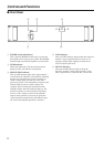
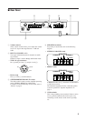
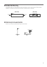
■ Rear Panel
SPEAKERS
CHANNEL B CHANNEL A
INPUT
CHANNEL B CHANNEL A
GG
(BRIDGE)
(PARALLEL)
BRIDGE
STEREO
BRIDGE
STEREO
432 5
CHANNEL B CHANNEL A
∞ 0
40
30
20
15
10
3
6
25
–dB
∞ 0
40
30
20
15
10
3
6
25
–dB
1
PARALLEL
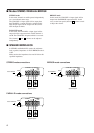
4 SPEAKERS terminals
For polarity in each mode, refer to the following
diagram.
• STEREO, PARALLEL mode
SPEAKERS
CHANNEL B CHANNEL A
BRIDGE
STEREO
• BRIDGE mode
SPEAKERS
CHANNEL B CHANNEL A
BRIDGE
STEREO
In BRIDGE mode, the (-) terminals of CHANNELS
A and B are not used.
The minimum impedance for the connected speaker
system is specified in “Speaker Impedance” on
page 4.
5 GND terminals
This is the grounding screw terminal. If hum or noise
occurs, ground (earth) the unit via this jack, or try
connecting it to the chassis of the mixer or preamp,
etc.
1 Volume controls
These volume controls allow you to adjust the volume
level in 31 steps in the range between –∞ dB and
0 dB.
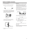
2 INPUTS (CHANNEL A, B)
Two types of balanced inputs for channels A and B
are provided.
Channel A input is used in Bridge and Parallel mode.
• XLR-3-31 type connectors
Pin 1–ground, pin 2–hot (
+
), and pin 3 cold (
-
).
1
2
3
Cold
GroundHot
• Barrier strip
Hot (+), Cold (-) and Ground (G).
3 STEREO/BRIDGE/PARALLEL switch
This slide switch is used to set the amplifier operating
mode: STEREO, BRIDGE or PARALLEL.
For details on the functionality of each mode, refer to
“Modes” on page 4.