


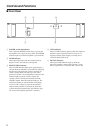

10
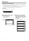
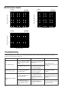
■ Performance Graphs
Mode:STEREO
Both ch Driven
RL=4Ω, f=1kHz
Mode:STEREO
Both ch Driven
RL=4Ω, f=1kHz
Mode:STEREO
Both ch Driven
RL=4Ω, f=1kHz
C160
C320C450
Output Power [W]
Power Consumption [W]
Power Consumption [W]
Output Power [W]Output Power [W]
Power Consumption [W]
1k100101
5k
1k
100
20
20
100
1k
5k
1 10 100 1k1k100101
5k
1k
100
20
Troubleshooting
The following table lists the main causes of abnormal operation and the corrective measures required, as well as the
protective circuit operation in each case.
Indicator Probable Cause Remedy Protection Circuit
Locate and correct the cause
of the short.
Use a speaker system with
an impedance of at least 4Ω
(stereo) or 8Ω (bridge).
Check the ventilation slots,
and improve the airflow
around the amplifier.
Check the amplifier ventila-
tion conditions and take
appropriate measures to
improve airflow around the
amplifier.
Consult your dealer or
nearest Yamaha service
center.
There is a short at a speaker
terminal, amplifier terminal,
or wire.
The amplifier load is exces-
sive.
The heat sink temperature
has exceed 85˚C.
The heat sink temperature
has exceeded 95˚C.
A DC voltage of ±2 V or
greater was generated in the
power amplifier’s output
circuit.
The PC limiter circuit
operates to protect the power
transistors.
Warning by the TEMP
indicator.
The thermal protection circuit
operates to protect the power
transistors.
The relay operates to protect
the speaker system.
CLIP indicator lights.
TEMP indicator lights.
PROTECTION indicator
lights.