


Page 12 Model PA435X
© 2003 Xantech Corporation
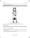
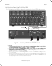
CAUTION: When operating in the BRIDGED mode (particularly when bench testing the amplifier) do not make a
ground or any other kind of connection to the amplifier speaker terminals other than those to the individual
speakers as shown. Failures caused by inappropriate connections are not covered under the warranty.
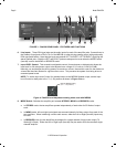
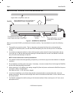
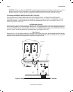
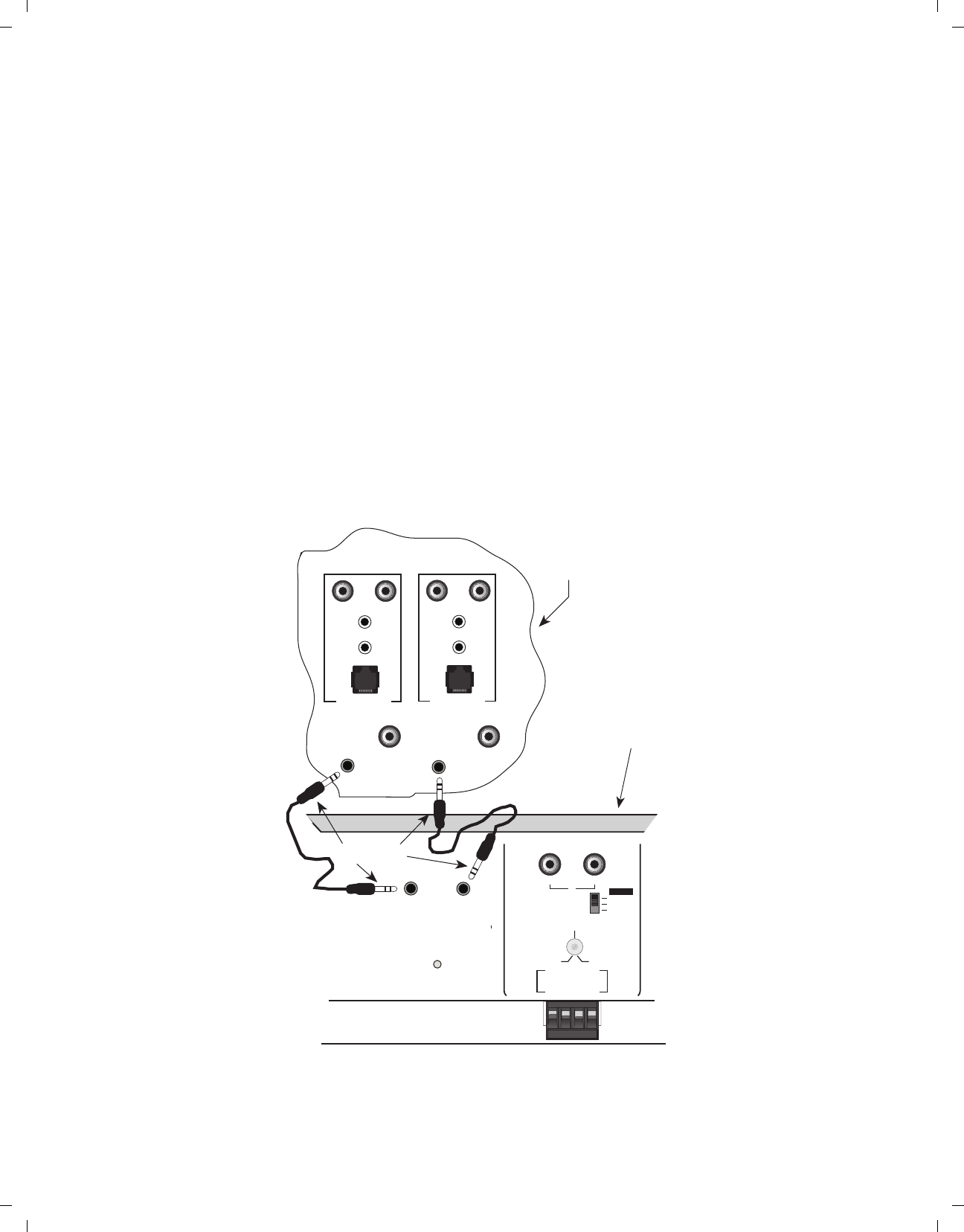
Connecting the REMOTE MASTER ON/OFF MUTE CONTROL
As mentioned under "PA435X PANEL AND FEATURE DESCRIPTIONS", the REMOTE MASTER ON/OFF
CONTROL inputs (CI1 & CI2) will allow the power to the PA435X to be turned ON, OFF, and MUTED by remotely
applied DC Voltages. Fig. 8 illustrates how a PA435X can be switched ON and OFF via the MRC88 Zone 7 & 8
Control Outputs (CO1 and CO2).
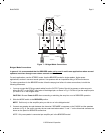
On/Off Standby Control:
Whenever a 5 to 30v dc voltage is applied to the TIP of the 3.5mm Stereo jack, the associated Amplifier channel will
be activated (Powered ON). When the signal applied to the TIP approaches GND it will put the associated Amplifier
channel in STANDBY Mode. If both Amplifier channels are in STANDBY MODE and the front POWER SWITCH left in
the OUT position, the entire Amplifier will be powered down (Illuminated LOGO OFF).
Mute Control:
Whenever a 5 to 30v dc voltage is applied to the RING of the 3.5mm Stereo jack, the associated Amplifier channels
signal output will be MUTED. When the signal applied to the RING approaches GND it will UN-MUTE the associated
Amplifier channel and the audio signal will be returned to its previous level.
LEFT RIGHT
SPEAKER
+-- --+
STEREO
MONO
BRIDGED
MODE
+ BRIDGED --
1V
.2V
3V
LEVEL
8
STATUS
ZONE IR
K
E
Y
P
A
D
PREAMP OUT
MRC88 Rear Panel
Zones 7 & 8
CI
1
CI
2
POWER
7
STATUS
ZONE IR
K
E
Y
P
A
D
PREAMP OUT
REMOTE AMP
CO1
VIDEO
OUT 8
VIDEO
OUT 7
REMOTE AMP
CO1
Use
3.5mm Stereo
Mini Plug Cables
PA435X
Rear Panel
LR
LEFT RIGHT
A
LR
Figure 8: Using the PA435X REMOTE MASTER ON/OFF CONTROL Terminals