


Page 6 Model PA4100X
© 2003 Xantech Corporation
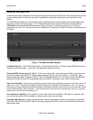
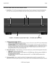
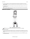
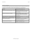
are currently in STANDBY MODE. Whenever the LOGO is not illuminated, this indicates the amplifier is
powered OFF.
5. Feet: Provides required ¾” spacing when unit is shelf mounted to allow for proper ventilation. These feet
should not be removed. (see the section entitled INSTALLATION for further information)
13
9
11
11
9
12
814
7
6 6
10
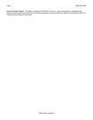
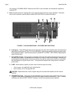
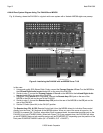
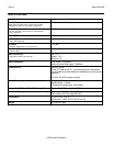
FIGURE 3 – PA4100X REAR PANEL - FEATURES AND FUNCTIONS
6. Line Inputs. These RCA-type jacks are the audio inputs for each of the amplifier pairs. Connect them to
the Preamp Output jacks of Zone 7 & 8 of the MRC88 (or other driving preamp output) with good quality
RCA-type patch cables. Note that the inputs are marked LEFT-A-RIGHT, LEFT-B-RIGHT signifying the
stereo channel pairs.
7. Input LEVEL Control. This screwdriver adjustable control (for each stereo pair) allows the input level for
full rated power output to be adjusted over a range of 0.2 volts to 3 volts (24.3 dB range). Normally you
would adjust the driving preamp to maximum volume, then set this control to the maximum volume that
the client desires for a given zone or room. This prevents the system from being driven to unwanted
power levels.
8. FUSE. When required, replace only with a fuse of the same type and rating:
120 V Version: 10.0 AMP 250 VAC, SLOW BLOW.
240 V Version: 5.0 A Time-Lag 250 VAC.
CAUTION: Replacement with a fuse of higher rating will not protect the amplifier and will void the
warranty.
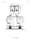
9. SPEAKER Terminals. These plug-in 4-terminal screw type connectors permit speaker wire sizes up to
12 gauge. When making connections for the STEREO mode, be sure to observe the "+” and "–" polarity
markings, just under the LEFT & RIGHT markings, for each wire pair going to the speakers.