


Page 17
Page 17 of 30 DVR395/DVR396-002
SECTION 2
POWER ON PROCEDURES
2.1 GENERAL
This section provides information and procedures for powering up the unit.
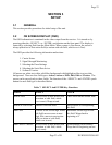
2.2 CONTROL DIP SWITCHES
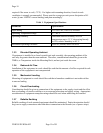
A four position DIP switch on the rear panel provides manual control and setup selection. Mode
setting is as follows: (In setting the DIP switches, "D" = down and "U" = up, "X" = don't care
for this function).
Table 4. Control DIP Switch Functions
Mode Function
1 2 3 4
Setup Functions
U X X X NTSC Video System*
D X X X PAL Video System*
X U X X Modulator Channel 3 (MODEL SPECIFIC)
X D X X Modulator Channel 2 (MODEL SPECIFIC)
X X U X Normal video
X X D X Color Bars, Tones
X X X U LNB Power OFF
X X X D LNB Power ON
Set the switches to the settings appropriate for your system.
* The receiver must be set to the same format (NTSC or PAL) as the desired channel being
received. The receiver will not operate correctly with incompatible settings.
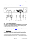
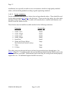
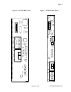
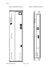
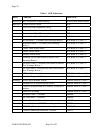
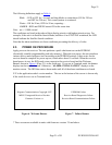
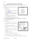
2.3 FRONT PANEL CONTROLS AND INDICATORS
The front panel indicators and controls are shown in Figure 4 (Page 18) and Figure 5 (Page 18),
and described in Table 4
(Page 17).