


Page 14
DVR395/DVR396-002 Page 14 of 30
1.5 SECURITY LABELS
The DVR395 incorporates security labels. There are no user serviceable components within the
IRD (integrated receiver decoder). Tampering with the security labels, opening the units, will
void your warranty. If you have questions, contact Wegener's customer service department at the
address and phone (fax) numbers shown in Section 1.6 (Page 16) of this manual.
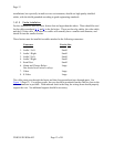
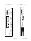
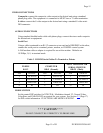
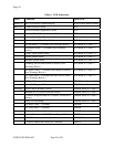
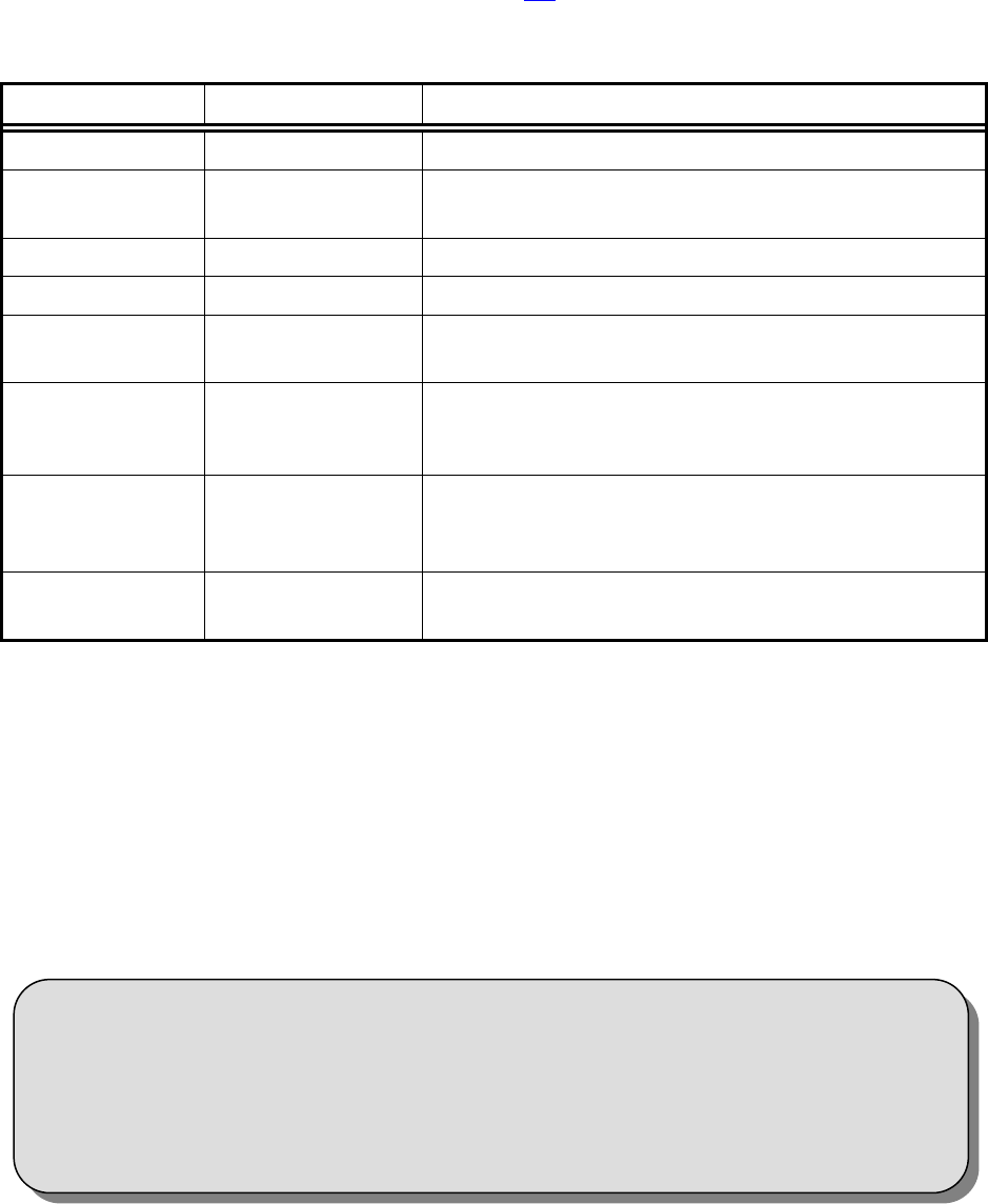
Table 2. DVR395/DVR396 Interconnect Descriptions
Signal Connector Description
RF IN F 950 to 2150 MHz signal accepted
COMPOSITE
VIDEO OUT
Phono Jack NTSC or PAL
S-VIDEO OUT S-video NTSC or PAL
AUDIO OUT Two phono jacks Audio stereo
SERIAL PORT RJ-12 Serial Asynchronous Data. May be used for terminal,
printer, modem, or local COMPEL control.
MODE SWITCH 4 Position DIP
Control DIP switches for NTSC/PAL; Modulator
channel 2/3; Normal Video, Color Bars; and LNB
Voltage ON/OFF.
ALARM Terminal Strip Receiver alarm contacts,
Alarm : NC connects to COM
NORMAL : NO connects to COM
CLOSURE Terminal Strip Solid state switch closures defined by the network
control systems or equipment status.
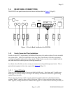
Connect the receiver to the desired equipment as follows:
CHASSIS GROUND
Using #12 AWG or larger wire, connect the ground to a system or rack ground.
RF IN
Using 75 Ohm coaxial cable with a type F connector, connect your RF source to the RF
IN connector.
* * * CAUTION * * *
When connecting cables to “F” type connectors apply a force of no
more than 12 inch/lb. (Finger tight). Avoid connecting adapters
directly to “F” type connectors. Use at minimum a 1-foot flexible
extension cable between “F” type connectors and adapters.