


9
On AC50CP2, one of speaker outputs is used to connect internal speakers and another socket
can be used to connect extension speaker system. (We recommend VOX model V212BN 2 x 12”
speaker cabinet as a perfect match with this combo amplifier). Please remember that the internal
speakers are wired for 16 ohm. In case you use the internal and V212BN together, please set the
Impedance Selectors Switch to 8 ohm.
Any other combination other than described here CANNOT be used.
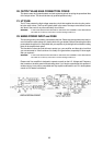
17. EFFECTS LOOP
The series effects loop is situated between the outputs of the preamp stages and the input of the
Reverb stage. The signal is then fed into the power amp stage. The BYPASS slide switch will
either engage the loop (switch ON) or disconnect the effects loop circuitry from the rest of the
amplifier (switch OFF). We recommend that if you are not using the loop then the switch should
be set to the OFF position.
With the LOOP switch in the OFF position, the SEND jack socket is still operational and can
therefore be used to send the signal to another device such as a tuner or slave amplifier.
The LOOP LEVEL Switch allows the loop to be used at two different signal levels (approximately
+4dBV (high) and -10dBV (low)). This will enable a wide range of devices to be connected to the
amplifier. We do not recommend the use of stomp box devices in a loop, particularly Fuzz and
Distortion pedals as these can limit the headroom of the amplifier and prevent you achieving full
power output.
18. DIRECT OUT
The AC50/100CP amplifier has a very comprehensive DI circuit, as explained earlier in this manual.
Please refer back to the note 13 (Output Master Volume control) which explains the relationship
between the DI circuit and the amplifier.
The DI is outputted on either Balanced XLR or Unbalanced Jack connection and both are con-
trolled by the LEVEL rotary control. The GROUND LIFT Switch will either connect the external
equipment to the AC50/100CP direct grounding or to a phantom ground circuit to prevent ground
loops occurring, please try both positions for best performance.
The LPF (Low Pass Filter) switch will change the DI response to either the normal amplifier
frequency response for use when connecting to slave amplifiers and guitar type speaker sys-
tems, or, when switched on, will introduce a very sharp filter network that removes the high
frequencies that are normally removed by guitar loudspeakers. This enables the amp to be di-
rectly connected to PA or recording equipment and speaker emulated sounds to be achieved.
Please remember that by turning the Master Volume to 0 you can silent “record” from the DI
output. It is HIGHLY RECOMMENDED that when doing so that the amplifier is still connected to
the normal loudspeaker system so that if the Master is accidentally turned up then no damage
can occur to your amplifier.
19. FOOTSWITCH JACK
This jack is for connecting the supplied VF002 double footswitch to the amplifier for remote
channel (switch A) and reverb switching (switch B).
If you require to use an alternative switching system (MIDI switcher for instance) then the follow-
ing information will be of use: -
Both switches are short to ground - Channel switching = jack Tip – channel 1 is closed – channel
2 is open – Reverb = jack Ring – reverb off is closed – reverb on is open. Approximately 7.5Vdc
@ 10mA is present on open switches.