


8
playing through a low power valve amp. Another benefit of this type of circuit and control (as
mentioned in the introduction) is that the DI circuit is connected between the phase inverter valve
and the Output Master Volume. This not only gives the DI the tone of the power amp, but the DI
and power output control are totally independent.
14. STANDBY SWITCH
The standby switch is used to a) turn the amplifier on or off for short durations such as breaks
when you do not want to go through the required warm up period, and b) it is used to alleviate
strain on the amp’s output valves when you are powering up from cold i.e. when warming up the
amp.
Historically the operation of the Standby switch is actually converse from its On & Off markings.
Standby OFF means that the amp is switched INTO Standby and the amplifier is not operating,
and Standby ON means the amp IS working. The Green LED indicator above the Standby switch
will illuminate when the amplifier is ON.
15. POWER SWITCH
This switch turns the mains power coming into the amp on or off. When the amp is active the Red
LED above the switch will be illuminated.
The correct procedure for powering up your AC50/100CP amplifier (and indeed virtually every
valve guitar amp made) is A) Check that the amplifier’s rating is suitable for the mains power that
you are using (i.e. a 230V rated amp is going to be connected to 230V mains power, 120V to
120V etc, if in doubt please consult your VOX dealer), B) ensure that all cables (speaker, footswitch,
FX loop, etc) are already connected, C) ensure MAINS and STANDBY switches are in the OFF
position and then connect the mains power cord to the amplifier, D) turn ON the POWER switch
and ensure that the RED LED is ON, E) wait for at least 2 minutes for the valves to warm up, and
then F) turn ON the STANDBY switch. Your amplifier is now ready for use. Allowing the amplifier
to warm up in this way will ensure that the valves are not subjected to too much stress and will
help them to achieve maximum life.
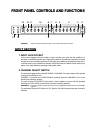
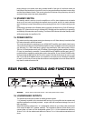
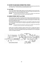
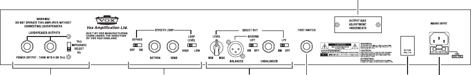
REAR PANEL CONTROLS AND FUNCTIONS
16
17
19
21
22
18
20
WARNING! Panels shown are for Head variants – CP2 combo panels read in reverse.
16. LOUDSPEAKER OUTPUTS
Two parallel connected jack sockets for feeding speaker system.
* It is extremely important to the continued safe running of your amplifier that the speaker and
amplifier impedances are closely matched – output valve and transformer damage can occur if
this is not done!
With AC50/100CPH, please use 1 or 2 loudspeaker cabinets of your choice (We recommend
VOX model V412BN 4x12” speaker cabinets). The Impedance Selector Switch allows you to
connect either a 16 ohm or 8 ohm loudspeaker system. For 1 x 16 ohm cabinets set selector to
16 ohm. For 2 x 16 ohm cabinets set selector to 8 ohms. For 1 x 8 ohm cabinets set selector to 8
ohms.