


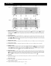

Power LED indicator
It is possible to operate the E 111 and E 112 equalizers while the LED remains lit. While the LED is OFF, the
signal fed to the rear-mounted input connector or jack is delivered to the output connector or jack
as it is.
Power switch
Pushing this switch causes the power to light and puts the equalizer in the operation mode. By
again pushing the switch, the power LED can be extinguished, permitting the input fed to the rear-
mounted input connector or jack to be delivered to the output connector or jack as it is.
Tampering protection cover
Prevents accidental move of switch or control that has been set. Always fit the cover in place except when
it needs to be removed for adjustment.
E 1 1 1
E 112
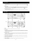
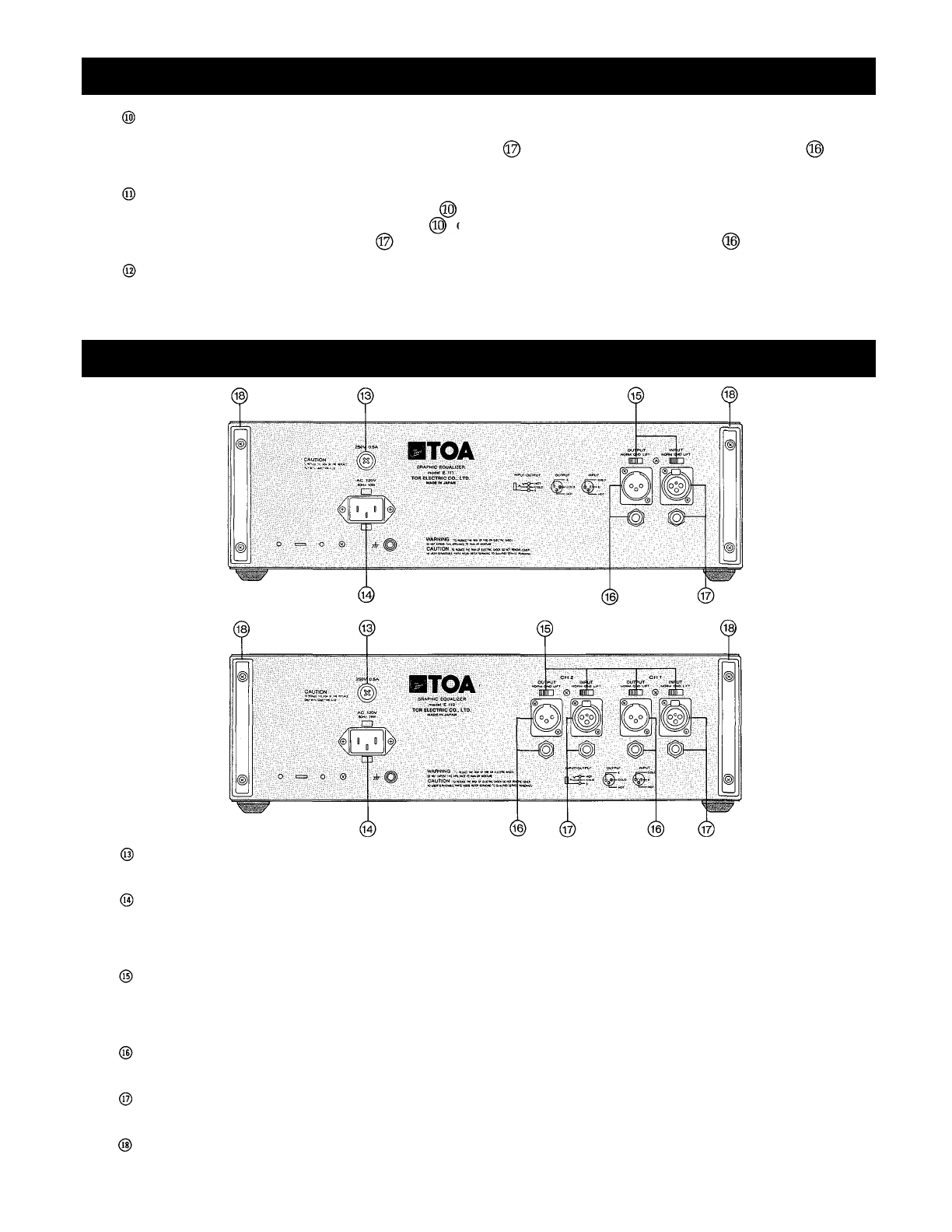
Fuse
Be sure to use the fuse of same type and capacity as are instructed.
Power inlet
An accessory power cord connects here. A use of the U-shaped clamp supplied with the equalizer by
inserting it into the holes provided above and below the power inlet is recommended to prevent accidental
disconnection of the power cord.
Ground lift switch
The
switch
is
used
to
avoid
earth
loop
that
causes
hum
noise
when
the
equalizer
(E
1ll/E
112)
is
connected to other equipment. By shifting the switch to the LIFT position, the earth loop may be cut.
Normally, set the switch to NORM.
Output connector and phone jack
A balanced type connector and jack with output impedance of 600 ohms. Both are wired in parallel.
Input connector and phone jack
A balanced type connector and phone jack with input impedance of 10k ohms. Both are wired in parallel.
Power cord hangers
Wind
the
power
cord
onto
the
hangers
when
the
equalizer
(E
1ll/E
112)
is not in
use.
— 6 —
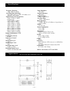
Front Panel
Rear Panel
LED