3
REVERSE SWITCH
Pushing REVERSE SWITCH, the display will indicate "ron" (REVERSE ON),LED above this switch light on. pushing this switch
once more ,reverse function is canceled and the display indicate "rof"(REVERSE OFF), the LED light off.
4
MOTOR OFF SWITCH
Pushing this switch, the motor is disconnected from the servo drive and the turntable turns to until it stops naturally, and itis
possible to change rotation motion of turntable by touching the side of turntable. The display will indicate "Sof" (SERVO OFF).
Pushing this switch once more, the function of MOTOR OFF is canceled and the display indicates "Son"(SERVO ON). in condition
of MOTOR OFF, Function of pitch fader, stick controller, reverse start/stop etc.....are canceled.
5
QUARTZ LOCK SWITCH
Pushing this switch , LED above this switch light on. The pitch is returned automatically to the predetermined speed (33-1/3 or
45rpm) in regardless of position of PITCH CONTOROL FADER VOLUME. At this time ,the display indicates "Q ON" (QUARTZ
ON) for 1 second. After that ,it indicates the value of pitch as "+00.0". By pushing this switch once more, the quartzlock is canceled
and the LED lights off. Then the display indicates "Q OF" (QUARTZ OFF). In quartzlock, pitch bend function of stick controller is
canceled. In case of power switch being on, beginning set is quartzlock off at 33 rpm.
6
STICK CONTROLLER
Moving the stick controller to the left ,the display indicate "FAS" (FAST) ,stick controller function is FAST FORWARD (FF), the
pitch speed is up momentarily. Moving the stick controller to the right, the display indicate "SLO" (SLOW) ,stick controller
function is SPEED DOWN ,the pitch speed is down momentarily. In quartzlock this function is still efficiency.
DIGITAL CONTROL
10
1
3
5
6
4
2
7
1
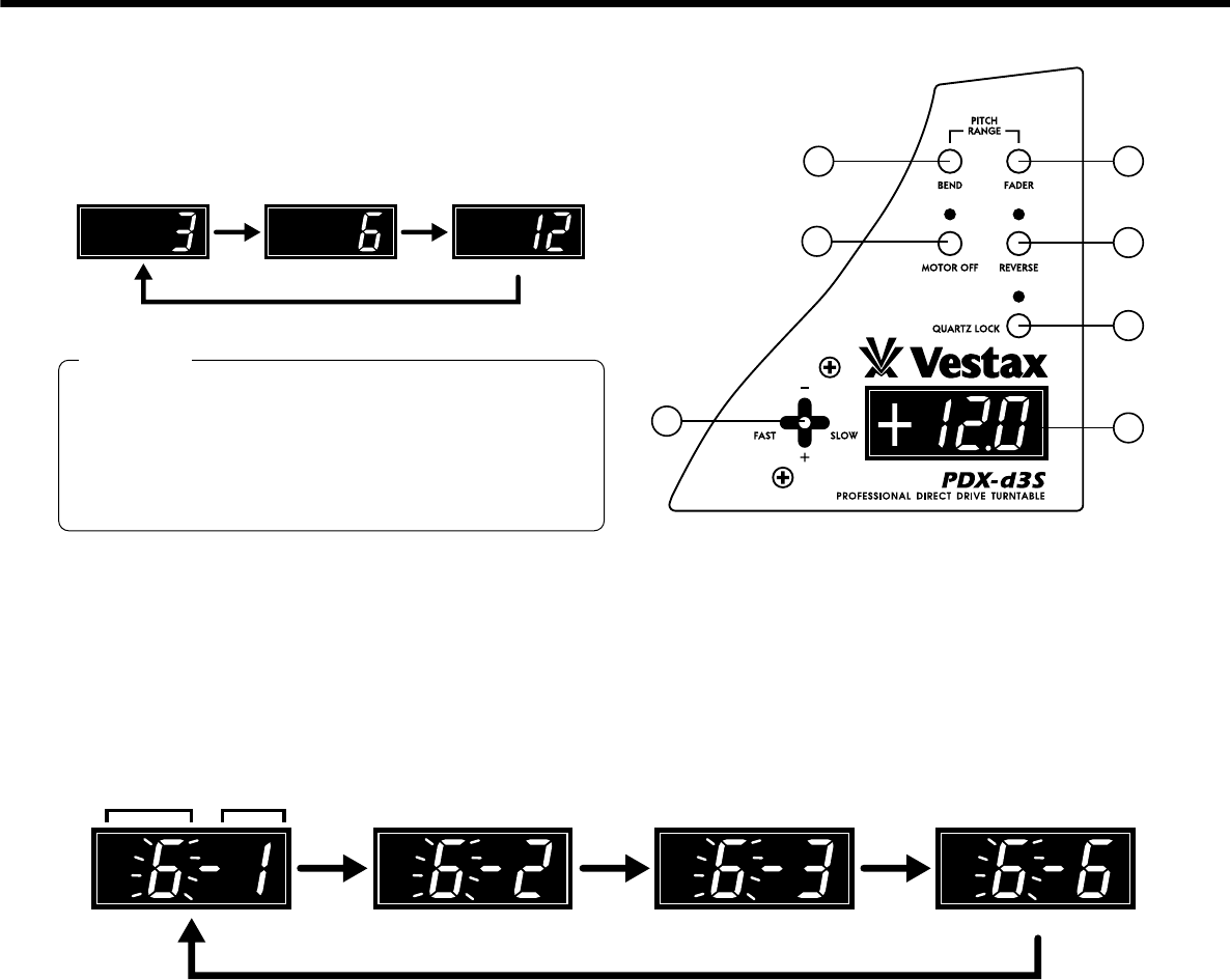
FADER PITCH SPAN SELECT SWITCH
Pushing the switch, fader pitch span can be selected between
3%, 6%, 12%. while watching the display
7
,
push this
switch continuously until the indicated value of span to select
snd stop pushing. refer to fig.1
2
PITCH BEND RANGE SELECT
Moving the stick controller down, the pitch speed is set in minus direction. Moving the stick controller up, the pitch speed is set in
plus direction. The pitch bend span is set by PITCH BEND RANGE SELECT SWITCH, left glimmering number ranks with right
blinking number fig2. Number fig2 on the left side the display is number to be set. Number on the right side display is number
newly selected. Pushing this switch continuously to the indicated number will set the right side of display. Then the left side
numbers changes to lighting and left side number is same as right side number. After setting, the display returns to indicate the velue
of pitch speed. Through, in setting another function is canceled.
fig1. FADER PITCH SPAN SELECT SWITCH
fig2. PITCH BEND RANGE SELECT
When the display return to pitch meter selected
value of span is set. but the value of span has
error 0.9% because of limit of electric function.
The display indicate the value of pitch exactly. So
that value will be indicated of the display than the
position of PITCH FADER VOLUME.
NOTE
current next


