


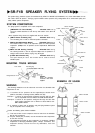


SR-F1B SPEAKER FLYING SYSTEM
This speaker flying hardware system is manufactured by ATM FLY-WARE™ (ATM GROUP, Inc.) of the United States for use
with TOA's SR-F1B speaker. The flying system enables various speaker array configurations to be constructed quickly and
safely without special components.
SYSTEM COMPOSITION
The flying system is comprised of five main components.
1 .[AMFS-SRF1-TH Truss Module] Allowable load 275 kg
The truss module attaches to both the top and bottom of the SR-F1B
speaker.
<Note> Speaker fixing screws are supplied with the truss module.
2 .[AMFS-1X2-30 Connecting Bar] Allowable load 278 kg
The connecting bar is used for horizontal speaker connection.
3 .[AMFS-1X2-SME Shackle Mount] Allowable load 225 kg
The shackle mount is used to set suspension points for vertical speaker
suspension.
(Multiple
rows
of
speakers
can be
suspended
at
different
tilt
angles.)
4.[AMFS-1X2-SB Stacking Bracket] Allowable load 194 kg
The stacking bracket is used to suspend multiple rows of speakers in a
straight vertical format without varying
array
tilt
angles.
5 . [2.5QRP Quick Release Pin] Allowable load 835 kg
The quick release pin has a lock function and is used to connect
individual parts.
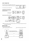
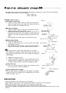
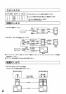
MOUNTING TRUSS MODULE
Truss module
Pan fitting ring
Hexagon bolt 3/8" x 41/2"
Caution
Never use mounting
hardware other than
supplied.
WARNING
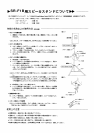
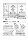
EXAMPLE OF USAGE
The following limitations must be observed even when the allowable load
requirement is met.
(1) A maximum of four speakers can be suspended per shackle mount
(AMFS-1X2-SME) or stacking bracket (AMFS-1X2-SB).
Example 1: A column of eight speakers configured two high and four wide
can be suspended from two AMFS-1X2-SME Shackle Mounts.
Example 2: A column of ten speakers configured two high and five wide
would require suspension from a minimum of three AMFS-1X2-
SME Shackle Mounts.
(2) A maximum of three rows of speakers using this flying hardware system
may be suspended in the vertical plane.
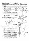
Confirm the following points before installation.
(1) Total actual load of each component must be lower than the allowable
load for that component.
(2) All quick release pins (2.5QRP) must be inserted into other components
to lock them securely.
(3) All components that relate to array suspension (i.e. enclosures, individual
components of the flying hardware system, clamps, connectors, and
suspension devices) must be free from any deformation, crack and
corrosion.
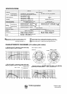
AMFS-1X2-SME
AMFS-1X2-SB
AMFS-1X2-SME
AMFS-1X2-30
AMFS-1X2-SME
AMFS-1X2-SME
2.5QRP AMFS-1x2-30
AMFS-SRF1-TH
2.5QRP
2.5QRP
2.5QRP
AMFS-1X2-30
2.5QRP
AMFS-SRFI-TH
AMFS-1X2-SB
2.5QRP
AMFS-SRFI-TH
AMFS-1X2-SB
2.5QRP
2.5QRP