


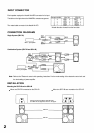
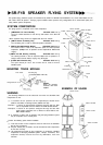

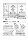

INPUT CONNECTOR
Each speaker employs the Neutrik NL4MPR connector for its input.
The table on the right shows the NL4MPR's contact arrangement.
The mated cable connector is the Neutrik NL4FC.
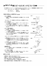
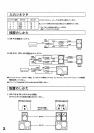
CONNECTION DIAGRAMS
Single System (SR-F1B)
* Woofer direction viewed from the front side.
Contact number
SR-F1B
SR-L1B
Combination System (SR-F1B and SR-L1B)
Mixer / preamplifier
Mixer/ preamplifier
Note: Refer to the "Electronic control unit's operating instructions" for the mode setting of the electronic control unit and
the level setting of power amplifier.
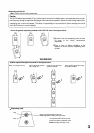
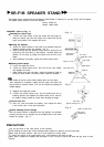
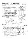
INSTALLATION
Mounting the SR-F1B on the SR-L1B
When one SR-F1B is mounted on the SR-L1B
When two SR-F1Bs are mounted on the SR-L1B
Arrange so the front edges of the SR-F1B
and SR-L1B are aligned as shown in the figure.
SR-F1B
SR-L1B
SR-F1B
SR-F1B
SR-F1B
2
SB-L1B