


4
FUNCTION CONTROL
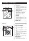
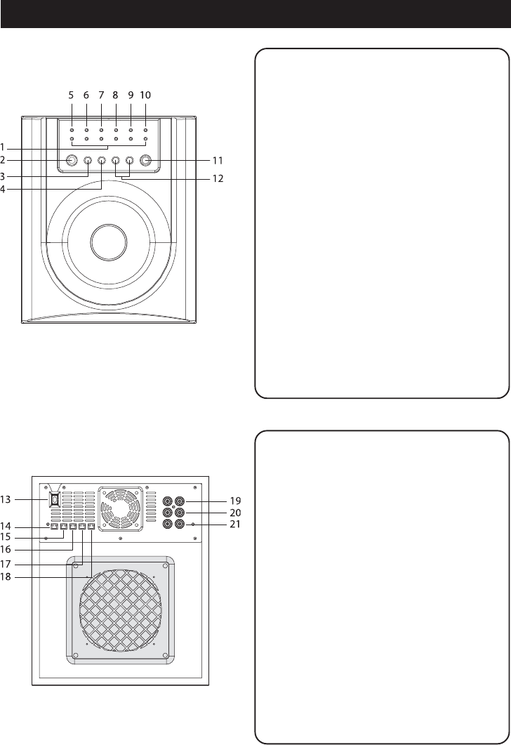
FRONT PANEL
BACK PANEL
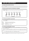
1. SPEAKER indicators
Lights when the corresponding speaker is active.
2. STANDBY/ON button
Turns the unit ON, or puts the unit into STANDBY
mode.
3. INPUT SOURCE button
Select the sound input source to AUX, GAME or
DVD.
4. SPEAKER CHANNELS button
Select 2.1 channel or 5.1 channel listening mode.
5. STANDBY indicator
Lights when the unit is in standby mode.
6. DVD indicator
Lights when the unit is in DVD mode.
7. GAME indicator
Lights when the unit is in GAME mode.
8. AUX indicator
Lights when the unit is in AUX mode.
9. 2.1 CHANNEL indicator
Lights when the listening mode is in 2.1 channel.
10.5.1 CHANNEL indicator
Lights when the listening mode is in 5.1 channel.
11.Remote Control sensor
Accepts the remote control signals.
12.VOLUME +/– button
Adjust the volume or the level of all speakers.
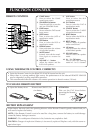
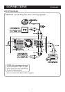
13. POWER CORD
Connect the power cord to the wall outlet.
14. RIGHT FRONT SPEAKER JACK
Connect the RIGHT FRONT SPEAKER to the RED
jack.
15. RIGHT REAR SPEAKER JACK
Connect the RIGHT REAR SPEAKER to the BLUE
jack.
16. CENTER SPEAKER JACK
Connect the CENTER SPEAKER to the YELLOW
jack.
17. LEFT REAR SPEAKER JACK
Connect the LEFT REAR SPEAKER to the GREEN
jack.
18. LEFT FRONT SPEAKER JACK
Connect the LEFT FRONT SPEAKER to the
WHITE jack.
19. AUX INPUT JACK
Connect to the audio out of other optional equip-
ment.
20. GAME INPUT JACK
Connect to the audio out of TV Game.
21. DVD INPUT JACK
Connect to the audio out of DVD player.