


Y
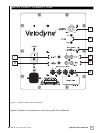
our new subwoofer is equipped with both speaker-level and line-level inputs. Use the
RCA/Phono type “INPUT” jacks when connecting your subwoofer to a pre-amp, signal
processor, or line-level crossover. The “SPEAKER LEVEL INPUT” jacks connect directly to the
speaker outputs of an integrated amplifier or receiver. Your amplifier section will notice no
additional loading effects when you use these inputs because of their high impedance.
Note: Do not use both the RCA/Phono “INPUT” connections and “SPEAKER LEVEL INPUT”
connections simultaneously.
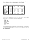
Low-Pass Crossover
Both sets of inputs sum the left and right channels together and the resulting signal is passed
through an adjustable low-pass crossover before being amplified. The crossover control allows
you to adjust the upper limit of the subwoofer’s frequency response from 40 to 120 Hz. The
subwoofer’s response will begin rolling off above the frequency you set this control to. (See note
above about frequency limits.)
You should set the crossover frequency to obtain a smooth and seamless transition from the
subwoofer to the main speakers in your system. Do this by listening to the blend between your
satellites and subwoofer using familiar material. If your main speakers are smaller units with
limited low frequency output, you may wish to choose a higher frequency (such as 100 -120 Hz)
than you would with larger speakers which have greater low frequency output. With larger
speakers, you might start with this control set lower, such as 70 Hz.
Subwoofer Direct
Subwoofer Direct is the leftmost setting on the low-pass crossover knob and will allow
frequencies up to 200 Hz into the subwoofer. If you ar
e not using an external crossover
, we
recommend that you use the one provided within the subwoofer for optimum performance.
Caution!!!
To avoid damage to your main amplifier, be sure to maintain correct polarity when making all
connections. Red (positive) to red, and black (negative) to black. Be sure that all connections
are tight, and that there are no loose strands or frayed wires.
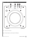
Power Switch
The master power switch is located on the middle left half of the unit. This rocker style switch is
the main on/off for the unit. This switch should be set to position 1 for on (up), 0 for off (down).
9
.
www.velodyne.com
Optimum User’s Manual
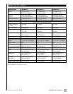
Rear Panel Connections - Detailed Explanation