


8
.
www.velodyne.com
Optimum User’s Manual
F
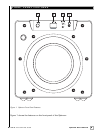
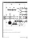
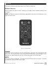
ollowing are brief descriptions of the connections described in Figure 2. More detail on these
connections can be found in the next section.
(1) LOW-PASS CROSSOVER
Use this knob to select the frequency above which you wish to roll off the signal to the
subwoofer. When the knob is turned all the way to the left, the Subwoofer Direct feature
is invoked and the subwoofer plays all frequencies up to 200 Hz.
(2) VOLUME Control
This control allows you to balance the output from the subwoofer to the main speakers in
your system. This control should be set to achieve similar volume level from between both
the main speakers and subwoofer. When pressing volume up or down, set the level while
watching the LED display for reference. The upper button increases the subwoofer level and
the lower button decreases it.
Note: Volume is also controllable by using the supplied remote. When defaults are restored,
the default volume setting is 30 out of 80.
(3) AUTO ON/OFF Switch
Use this switch to select between auto-on (active) and constant on (auto-on
inactive) operation.
(4)
LINE OUTPUT
Connect these jacks to the LINE IN amp input to use the Optimum subwoofer’s internal high
pass crossover. See below for a more detailed explanation of this crossover.
(5) LINE INPUT/LFE Input
Connect these jacks to the LINE OUT pr
eamp output, LFE output or subwoofer output jacks
of your receiver/processor. If using the LFE output from your receiver or processor, plug
the single cable into the “L” - LFE input or for more signal, use a “Y” connector (not included)
and feed the signal into both “R” and “L” inputs.
(6) SPEAKER LEVEL INPUT Terminals
Connect these input terminals to the speaker output terminals of your amplifier or receiver.
If you use this method of connection, when you go to the receiver speaker set up menu,
make sure you select the large speaker option.
(7) IR Input
This is a connection to allow you to pur
chase a thir
d-par
ty infrar
ed r
emote sensor or an
extended cable for placement closer to your other remote controlled equipment. This keeps
you fr
om awkwar
d control angles using the infrared remote control.
(8) 12v Trigger
When this mini jack is connected, the unit remains in power-off mode until 12 volts is
supplied across the two leads. There is no polarity requirement.