


user manual
QLight™ DP series
QLight DP series manual
page 26
MAINTENANCE
If any of the drive units should cease functioning you are advised to remove the faulty unit from
the cabinet and send it to a professional service centre authorised to recone Turbosound
loudspeakers. This will ensure the continued high performance of your QLight™ series product.
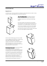
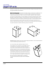
Removal of the low frequency driver – TQ-308DP, TQ-310DP, TQ-315DP
Unscrew the six countersunk socket head screws at the side of the cabinet that hold the protective
grille in place. Be careful when removing the grille as it is under tension and may spring outwards
when released. Set the grille and fixing screws aside for later re-assembly.
Undo the four Allen head bolts holding the driver in place, and carefully pull it out and away from
the cabinet. WARNING - this unit is heavy! Disconnect the cables from the loudspeaker terminals
and completely remove the driver from the cabinet. Make a note of the driver polarity for later
reconnection.
To reinstate the driver, simply reverse the procedure making sure you observe the correct polarity
when reconnecting the cables back into the terminals of the drive units.
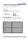
Removal of the HF unit – TQ-308DP, TQ-310DP
Remove the grille as described above. Set the grille and fixing screws aside for later re-assembly.
Unscrew the four Allen head bolts holding the high frequency range horn in place and carefully
pull it out and away from the cabinet. WARNING - this unit is heavy! Disconnect the cables from
the loudspeaker terminals and completely remove the driver from the cabinet. Make a note of the
driver polarity for later reconnection.
To reinstate the driver, simply reverse the procedure making sure you observe the correct polarity
when reconnecting the cables back into the terminals of the drive units.
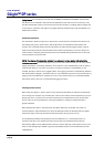
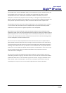
Removal of the 12”/1” driver – TQ-445DP
Unscrew the eight countersunk screws from the two vertical battens which hold the protective
grille in place. Be careful when removing the grille as it is under tension and may spring outwards
when released. Set the battens, grille and fixing screws aside for later re-assembly.
Undo the eight M6 x 30mm Allen head bolts holding the driver in place and carefully pull it out
and away from the cabinet. WARNING - This unit is heavy! You will notice that the 1” high
frequency driver is attached to the back of the 12” low frequency driver by its screw adapter.
Disconnect the cables from both HF and LF units and completely remove the driver assembly from
the cabinet. Make a note of the driver polarity for later reconnection.
Separate the drive units by unscrewing the high frequency driver anti-clockwise and lift it away