user manual
TA-880
TA-880 user manual
Page 70
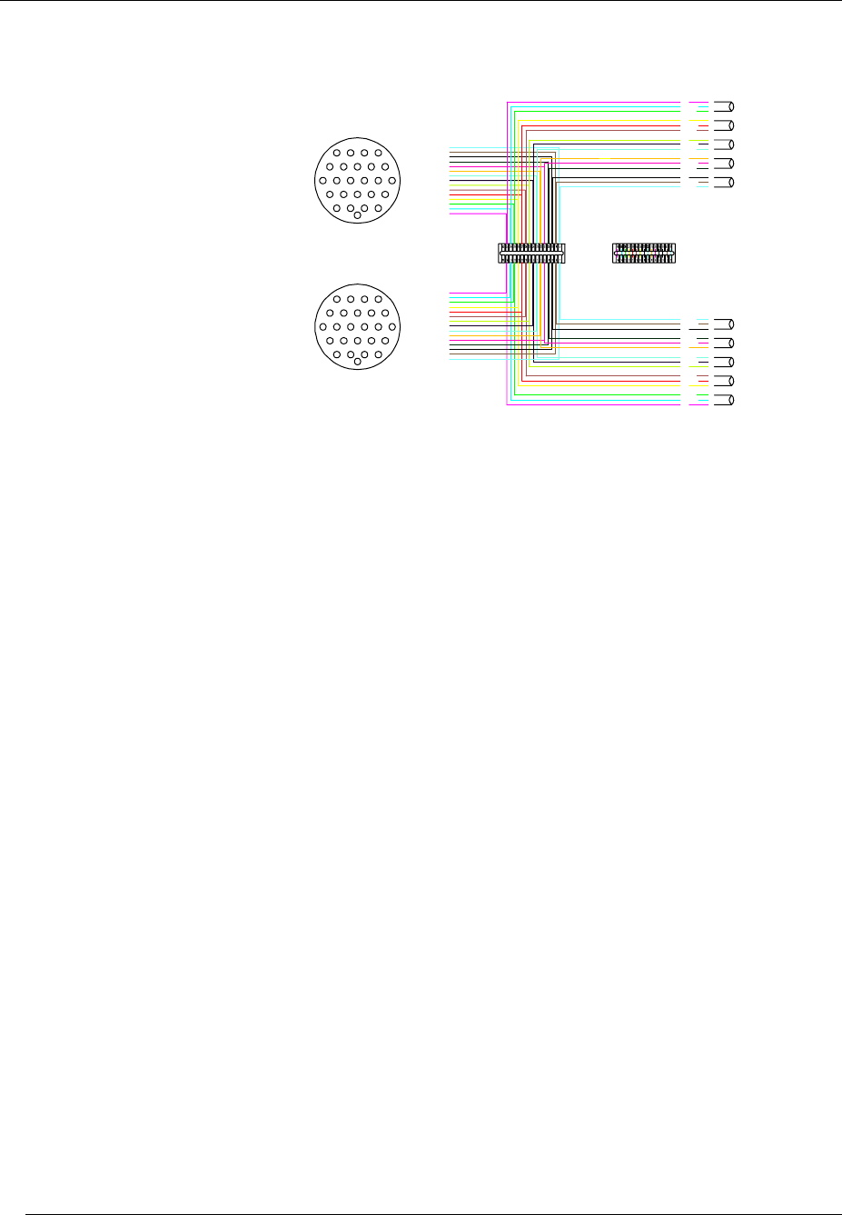
Figure 1. Amplifier Rack Signal Wiring
VDM
25 PIN
{
AMP SIGNAL
INPUT
INPUT
AMP SIGNAL
}
}
CHANNEL A
CHANNEL B
DCBA
WXYZ
RSTU
EFGH
MNPQ
J
V
LK
KL
V
J
QPNM
HGFE
UTSR
ZYXW
ABCD
A
E
F
G
C
B
D
H
J
M
L
K
Q
P
N
HIGH
BLUE
HI/MID
GREEN
LO/MID
YELLOW
BASS 1
RED
BASS 2
PURPLE
GND
COLD -v e
HOT +ve
GND
COLD -v e
HOT +ve
GND
COLD -v e
HOT +ve
GND
COLD -v e
HOT +ve
GND
COLD -v e
HOT +ve
HOT +ve
COLD -v e
GND
HOT +ve
COLD -v e
GND
HOT +ve
COLD -v e
GND
HOT +ve
COLD -v e
GND
HOT +ve
COLD -v e
GND
BASS 2
PURPLE
BASS 1
RED
LO/MID
YELLOW
HI/MID
GREEN
HIGH
BLUE
N
P
Q
K
L
M
J
H
D
B
C
G
F
E
A
Output Connections
The amplifier outputs are wired to two 19-way CEEP (Socapex compatible) output sockets,
rated at 20 Amperes per contact. The Socapex output wiring has been arranged to preclude
accidental connection of the mid-high output to anything other than the TA-890H, and of the
low frequency output to anything other than the TA-890L, preventing any risk of drive-unit
damage.
Two 4 metre fanouts are supplied to take the 19-way cable outputs to the speakers. The low
frequency fanout is fitted with six Speakon NL4FC connectors and the Mid-high fanout is
fitted with four Speakon NL8FC connectors. The cables are colour coded to indicate which
amplifier channels they relate to. Mating connectors are screw-locked, ensuring reliability.
In addition to the Socapex outputs, there are also separate local output connections for
running speaker systems not requiring multicore loudspeaker extension cables, for example
ground stacked systems.


