


user manual
LMS-A6
LMS-A6 user manual
Page 9
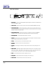
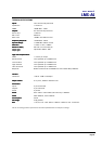
Connecting inputs and outputs
This section describes how to connect signals to the LMS-A6 loudspeaker management system.
The signal inputs are industry standard female XLR connectors and are wired as follows:-
Pin 1 = GROUND or COMMON
Pin 2 = HOT or (+) or In-phase
Pin 3 = COLD or (-) or Out of phase
The electronically balanced inputs will take a maximum level of +20dBu at 10k ohm impedance.
They will accept either balanced or unbalanced signals.
The signal outputs are industry standard male XLR connectors and are wired as follows:-
Pin 1 = GROUND or COMMON
Pin 2 = HOT or (+) or In-phase
Pin 3 = COLD or (-) or Out of phase
The output impedance is less than 100 ohms and the maximum signal level is +20dB. The
electronically balanced output stage will drive either balanced or unbalanced loads.
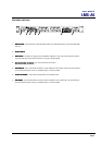
THE POWER SUPPLY SECTION
The power supply section includes an IEC connector, ON/OFF switch and an AC fuse.
Check that the voltage label corresponds with your local mains supply and that the correct AC fuse
is fitted. If it does not, contact your Turbosound Dealer for instructions on setting the LMS-A6 to
the correct voltage.
Connecting to the wrong voltage may damage the unit.
Connecting to the wrong voltage may damage the unit.Connecting to the wrong voltage may damage the unit.
Connecting to the wrong voltage may damage the unit.
The unit must be switched OFF before inserting or removing the mains cord.
When the system is powered and turned on, the green POWER LED on the front panel lights. If the
LED fails to light when power is applied and switched on check and, if necessary, replace the AC
fuse. If this does not solve the problem then an internal fuse may have blown. This indicates that
the unit has a fault and you should contact your Turbosound Dealer for further advice.