user manual
LMS-A6
LMS-A6 user manual
Page 6
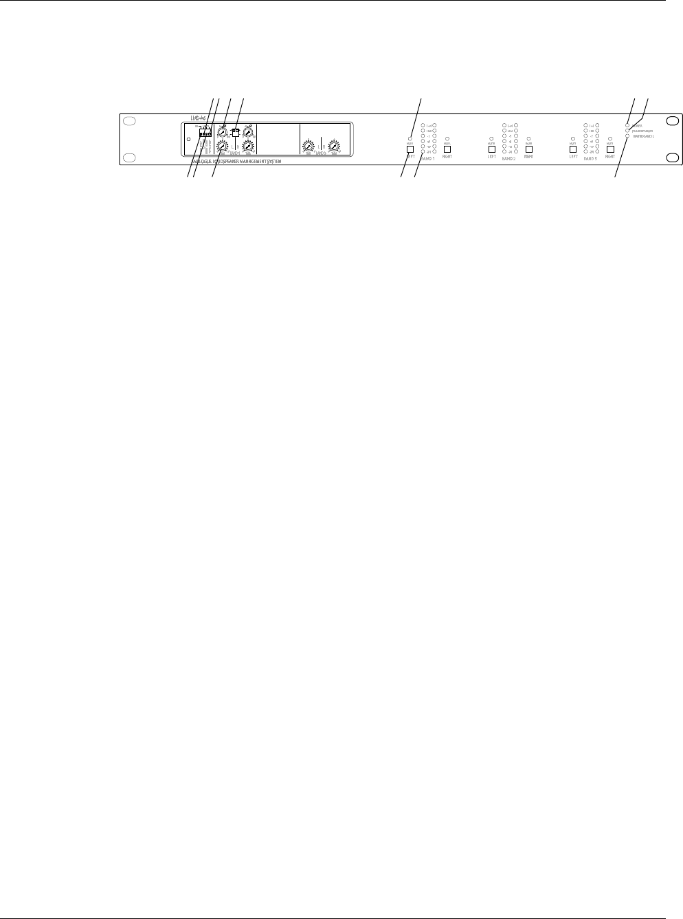
FRONT PANEL FUNCTIONS
1. Mono Band 1
Mono Band 1Mono Band 1
Mono Band 1 – sums the Left and Right Band signals together (up position) and feeds them in
mono to both Band 1 outputs.
2. Limiter cancel
Limiter cancel Limiter cancel
Limiter cancel –
disables all limiter functions and causes the LIMITER CANCEL LED to light.
3. Power Standby switch
Power Standby switchPower Standby switch
Power Standby switch – determines the power-up mode: in the up (cancel) position the unit
automatically switches out of mute after six seconds; in the down position the unit remains in
standby mode with all outputs muted.
4. Remote Standby cancel
Remote Standby cancelRemote Standby cancel
Remote Standby cancel – enables (down position) or disables (up position) the REMOTE
STANDBY function. Inoperable if the remote stanby function has not been wired up.
5. Phase adjustment
Phase adjustmentPhase adjustment
Phase adjustment – variable adjustment between 0° and 180°.
6. Gain trim
Gain trim Gain trim
Gain trim – allows the band 1 gains and band 3 gains to be adjusted to match band 2 where
speaker/amplifier sensititvities vary for each band.
7. Polarity
Polarity Polarity
Polarity – reverses the polarity of the selected frequency band.
8. Mute LED
Mute LEDMute LED
Mute LED – indicates mute staus of the selected channel.
9. Mute key
Mute keyMute key
Mute key – one latching mute switch per output channel. Press to mute; press again to un-
mute.
10. Output meters
Output metersOutput meters
Output meters – LED ladder displays headroom before limiting occurs. The lower four green
LEDs indicate –24dB, -12dB, -6dB and –1dB respectively, with the orange ‘LIM’ LED set at the
limiter threshold for that channel. The top, red LED indicates 4dB of limiting.
11. Power
Power Power
Power – green LED indicates that power is applied to the unit.
12. Standy Mute
Standy Mute Standy Mute
Standy Mute – red LED indicates when the standby mute mode is set.
13. Limiter Cancel
Limiter Cancel Limiter Cancel
Limiter Cancel – indicates when the limiter cancel mode is set.
1
24 5 7 8
11 12
36 910
POL
13


