


user manual
LMS-A6
LMS-A6 user manual
Page 7
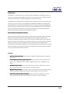
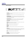
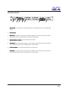
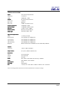
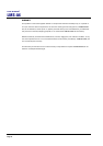
REAR PANEL FUNCTIONS
1. Mains Power
Mains PowerMains Power
Mains Power - Connected via a standard IEC socket. A compatible power cord is supplied with
the unit.
2. Power Switch
Power SwitchPower Switch
Power Switch.
3. Mains Fuse
Mains FuseMains Fuse
Mains Fuse - Located in a finger-proof fuseholder adjacent to the mains inlet. Always replace
this fuse with the correct type as shown on the rear panel legend.
4. Remote Standby connector –
Remote Standby connector – Remote Standby connector –
Remote Standby connector – for remote switch connection.
5. XLR Outputs
XLR OutputsXLR Outputs
XLR Outputs - 3 pin male XLR connectors are provided for each audio output. All terminations
are fully balanced, pin 2 Hot, pin 3 Cold and pin 1 Screen (shield).
6. Limiter threshold –
Limiter threshold – Limiter threshold –
Limiter threshold – sets limiter threshold for each output band.
7. XLR Inputs
XLR InputsXLR Inputs
XLR Inputs – 3 pin female XLR connectors are provided for each audio input. All terminations
are fully balanced, pin 2 Hot, pin 3 Cold and pin 1 Screen (shield).
ALWAYS USE SAFETY GROUND
AC 50/60Hz 40VA
S.No 10 - 1001 - A
NO USER SERVICEABLE PARTS INSIDE
230V
23 4 5 6
7
1