


PRECISION 8i
OPERATION MANUAL
6
UP-AND-RUNNING IN A HURRY
1. Read the “Safety and Operating Precautions”on page 2 of this manual.
2. Check the voltage selector on the International Power Supply Module (PSU-P8i) to
make sure it is set for the appropriate AC mains voltage in your area.
3. After making sure the main power switch is off, connect the AC power cord.
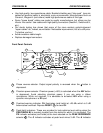
4. Connect output signal cables between PRECISION 8i and the analog line level
inputs of your recorder, mixer, signal processor, etc. Use either the individual 1/4”
TRS or DB25 eight-channel balanced output connectors. See the section
“Connections” for wiring details.
5. Connect mic cables to MIC 1 through MIC 8 as needed.
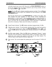
6. Connect the interface cable on the International Power Supply Module (PSU-P8i) to
the main PRECISION 8i unit.
7. Turn on the AC power.
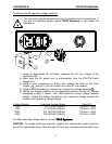
8. Set PEAK REFERENCE selector to +26.
9. Set 48V and buttons as appropriate on each channel.
10. Depress the RESET button to clear Peak-Hold indicators.
11. Adjust Gain controls for adequate signal level as indicated on the PRECISION 8i
level indicators or on the level indicators of the device to which it is connected.
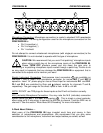
If you’re using the DI’s for electric instrument input:
1. Connect your instrument cables to Direct In 1 and Direct In 2 on the rear panel. The
Direct In jacks are located within the same connectors as MIC 7 and MIC 8. Simply
plug your 1/4” phone plug into the center portion of the desired connector. NOTE:
DO NOT use TRS plugs for these inputs as the DI will not function correctly.
2. Set buttons as appropriate.
3. Adjust DI-1 or DI-2 Gain controls for adequate signal level as indicated on the
PRECISION 8i level indicators or on the level indicators of the device to which it is
connected.
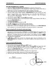
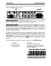
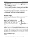
If you’re using the M/S Decoder:
1. Connect the cardioid or omni MID mic to MIC 1 input.
2. Connect the figure 8 SIDE mic to MIC 2 input. Face the SIDE mic toward the right
side of the sound field (perpendicular to the axis of the MID mic). See Figure 1.
3. Depress the MID-SIDE ON button. “Left” signal is routed to Channel 1 output. “Right”
signal is routed to Channel 2 output.
4. Adjust the Channel 1 gain control for adequate mono signal level.
5. Adjust the Channel 2 gain control to vary the image width as desired.
6. See the section “More About M-S Decoding” for more information.
Figure 1
M-S microphone orientation
MID
SIDE